Project Overview
1. Production Program
600 sets/day (117/118 bearing pedestral)
2. Requirements for processing line:
1) NC machining center suitable for automatic production line;
2) Hydraulic frock clamp;
3) Automatic loading and blanking device and conveying device;
4) Overall processing technology and processing cycle time;
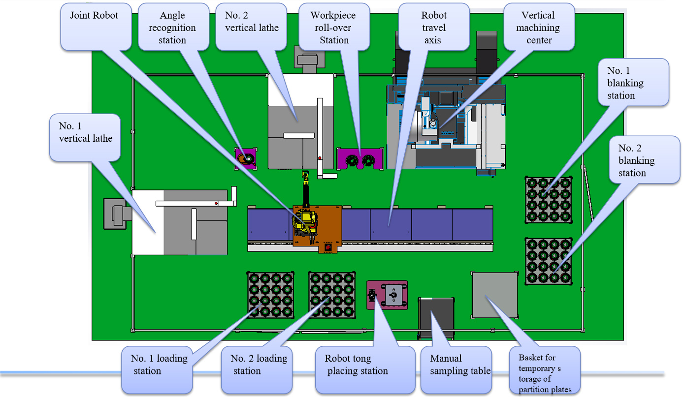
Layout of Production Lines
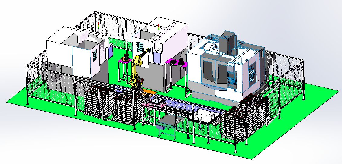
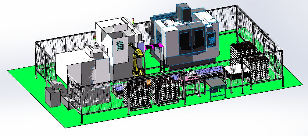
Layout of Production Lines
Introduction of Robot Actions:
1. Manually place the roughly machined and placed baskets on the loading table (Loading tables No. 1 and No. 2) and press the button to confirm;
2. The robot moves to the tray of No. 1 loading table, opens the vision system, grabs and moves Parts A and B respectively to the angular viewing station to wait for the loading instruction;
3. The loading instruction is sent out by the angular recognition station. The robot puts No. 1 piece into the positioning area of the turntable. Rotate the turntable and start the angular recognition system, determine the angular position, stop the turntable and finish the angular recognition of No. 1 piece;
4. The angular recognition system sends out the blanking command, and the robot picks up the No. 1 piece and puts the No. 2 piece in for identification. The turntable rotates and the angular recognition system starts up to determine the angular position. The turntable stops and the angular recognition of No. 2 piece is completed, and the blanking command is sent out;
5. The robot receives the blanking command of No. 1 vertical lathe, moves to loading and blanking position of No. 1 vertical lathe for material blanking and loading. After the action is completed, the single-piece machining cycle of vertical lathe starts;
6. The robot takes the finished products by No. 1 vertical lathe and places it at No. 1 position on the workpiece roll-over table;
7. The robot receives the blanking command of No. 2 vertical lathe, moves to loading and blanking position of No. 2 vertical lathe for material blanking and loading., and then the action is completed, and the single-piece processing cycle of vertical lathe starts;
8. The robot takes the finished products by No. 2 vertical lathe and places it at No. 2 position on the workpiece roll-over table;
9. The robot waits for the blanking command from vertical machining;
10. The vertical machining sends the blanking command, and the robot moves to the loading and blanking position of the vertical machining, grabs and moves the workpieces of No. 1 and No. 2 stations respectively to the blanking tray, and places the workpieces on the tray respectively; The robot moves to the roll-over table to grasp and send No. 1 and No. 2 pieces to the vertical machining loading and blanking positions respectively, and places No. 1 and No. 2 workpieces into the positioning area of No. 1 and No. 2 stations of the hydraulic clamp respectively to complete the vertical machining loading. The robot moves out of the safety distance of the vertical machining and starts a single processing cycle;
11. The robot moves to No. 1 loading tray and prepares for the startup of the secondary cycle program;
Description:
1. The robot takes 16 pieces (one layer) on the loading tray. The robot will replace the suction cup tong and place the partition plate in the temporary storage basket;
2. The robot packs 16 pieces (one layer) on the blanking tray. The robot should replace the suction cup tong once, and put the partition plate on the partition surface of the parts from the temporary storage basket;
3. According to the inspection frequency, make sure that the robot places a part on the manual sampling table;
|
1 |
The machining cycle timetable |
||||||||||||||
|
2 |
Customer |
Workpiece material |
QT450-10-GB/T1348 |
Model of machine tool |
Archive No. |
||||||||||
|
3 |
Product Name |
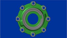
117 Bearing seat |
Drawing No. |
DZ90129320117 |
Date of preparation |
2020.01.04 |
Prepared by |
||||||||
|
4 |
Process step |
Knife No. |
machining content |
Tool Name |
Cutting Diameter |
Cutting speed |
Rotational speed |
Feed per revolution |
Feed by machine tool |
Number of cuttings |
Each process |
Machining time |
Idle Time |
Four-axis rotating time |
Tool change time |
|
5 |
No. |
No. |
Desoriptions |
Tools |
D mm |
n |
R pm |
mm/Rev |
mm/Min |
Times |
mm |
Sec |
Sec |
Sec |
|
|
6 |
 |
||||||||||||||
|
7 |
1 |
T01 |
Milling mounting hole surface |
Diameter of 40-face milling cutter |
40.00 |
180 |
1433 |
1.00 |
1433 |
8 |
40.0 |
13.40 |
8 |
4 |
|
|
8 |
Drill DIA 17 mounting holes |
DIA 17 COMBINED DRILL |
17.00 |
100 |
1873 |
0.25 |
468 |
8 |
32.0 |
32.80 |
8 |
4 |
|||
|
9 |
T03 |
DIA 17 hole back chamfering |
Reverse chamfering cutter |
16.00 |
150 |
2986 |
0.30 |
896 |
8 |
30.0 |
16.08 |
16 |
4 |
||
|
10 |
Description: |
Cutting time: |
62 |
Second |
Time for clamping with fixture and for loading and blanking materials: |
30.00 |
Second |
||||||||
|
11 |
Auxiliary time: |
44 |
Second |
Total machining man-hours: |
136.27 |
Second |
|||||||||
|
1 |
The machining cycle timetable |
|||||||||||||||||
|
2 |
Customer |
Workpiece material |
QT450-10-GB/T1348 |
Model of machine tool |
Archive No. |
|||||||||||||
|
3 |
Product Name |
118 Bearing seat |
Drawing No. |
DZ90129320118 |
Date of preparation |
2020.01.04 |
Prepared by |
|||||||||||
|
4 |
Process step |
Knife No. |
machining content |
Tool Name |
Cutting Diameter |
Cutting speed |
Rotational speed |
Feed per revolution |
feed by machine tool |
Number of cuttings |
Each process |
Machining time |
Idle Time |
Four-axis rotating time |
Tool change time |
|||
|
5 |
No. |
No. |
Desoriptions |
Tools |
D mm |
n |
R pm |
mm/Rev |
mm/Min |
Times |
mm |
Sec |
Sec |
Sec |
||||
|
6 |
|
|||||||||||||||||
|
7 |
1 |
T01 |
Milling mounting hole surface |
Diameter of 40-face milling cutter |
40.00 |
180 |
1433 |
1.00 |
1433 |
8 |
40.0 |
13.40 |
8 |
4 |
||||
|
8 |
T02 |
Drill DIA 17 mounting holes |
DIA 17 COMBINED DRILL |
17.00 |
100 |
1873 |
0.25 |
468 |
8 |
32.0 |
32.80 |
8 |
4 |
|||||
|
9 |
T03 |
DIA 17 hole back chamfering |
Reverse chamfering cutter |
16.00 |
150 |
2986 |
0.30 |
896 |
8 |
30.0 |
16.08 |
16 |
4 |
|||||
|
10 |
Description: |
Cutting time: |
62 |
Second |
Time for clamping with fixture and for loading and blanking materials: |
30.00 |
Second |
|||||||||||
|
11 |
Auxiliary time: |
44 |
Second |
Total machining man-hours: |
136.27 |
Second |
||||||||||||
|
12 |
||||||||||||||||||
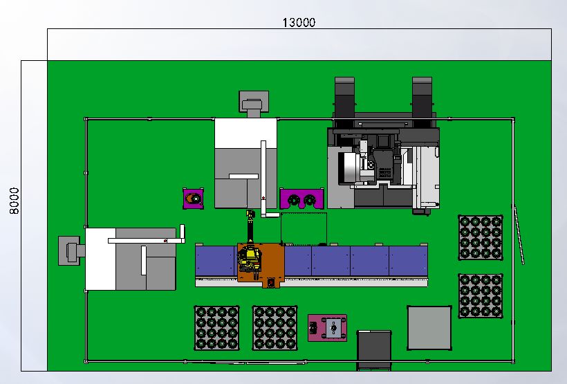
Coverage area of the production line
Introduction of main functional components of production line
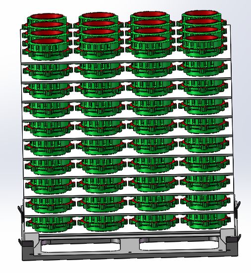
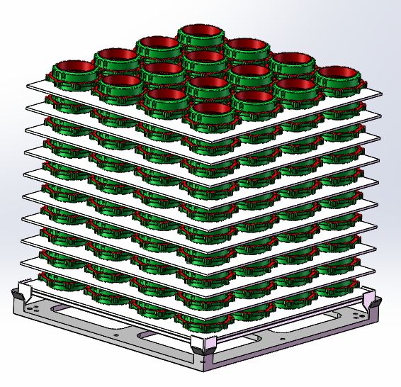
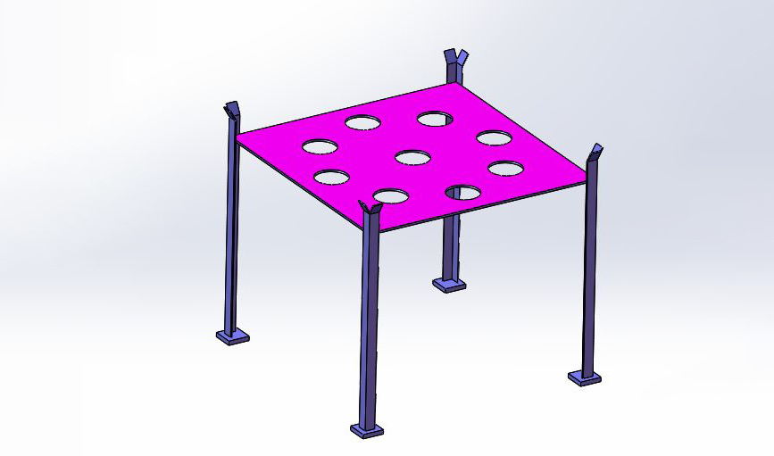
Introduction of the loading and blanking system
Storage equipment for automatic production line in this scheme is: The stacked tray (the quantity of pieces to be packed on each tray shall be negotiated with the customer), and the positioning of the workpiece in the tray shall be determined after providing 3D drawing of workpiece blank or the actual object.
1. The workers pack the roughly processed parts on the material tray (as shown in the figure) and forklift them to the designated position;
2. After replacing the tray of the forklift, manually press the button to confirm;
3. The robot grasps the workpiece to carry out the loading work;
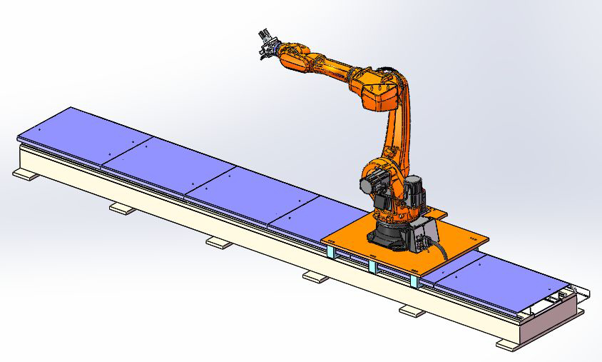
Introduction of Robot Travel Axis
The structure is composed of a joint robot, a servo motor drive and a pinion and rack drive, so that the robot can make rectilinear motion back and forth. It realizes the function of one robot serving multiple machine tools and gripping workpieces at several stations and can increase the working coverage of joint robots;
Traveling track applies the base welded with steel pipes and is driven by servo motor, pinion and rack drive, to increase the working coverage of the joint robot and effectively improve the utilization rate of robot; The traveling track is installed on the ground;
Chenxuan robot:SDCX-RB500
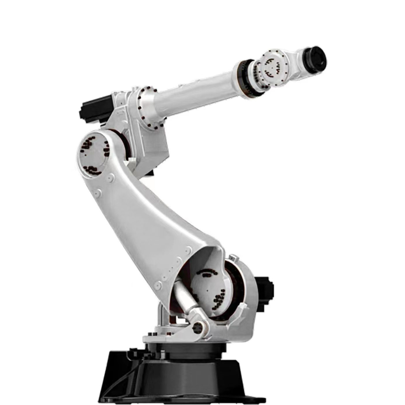
| Basic data | |
| Type | SDCX-RB500 |
| Number of axes | 6 |
| Maximum coverage | 2101mm |
| Pose repeatability (ISO 9283) | ±0.05mm |
| Weight | 553kg |
| Protection classificationof the robot | Protection rating,IP65 / IP67in-line wrist(IEC 60529) |
| Mounting position | Ceiling, permissible angle of inclination ≤ 0º |
| Surface finish, paintwork | Base frame: black (RAL 9005) |
| Ambient temperature | |
| Operation | 283 K to 328 K (0 °C to +55 °C) |
| Storage and transportation | 233 K to 333 K (-40 °C to +60 °C) |
With a wide range of motion domain at the back and bottom of the robot, being the model able to be mounted with ceiling lifting. Because the lateral width of the robot is reduced to the limit, it is possible to be installed closely to the adjacent robot, clamp, or workpiece. High-speed movement from standby position to working position and fast positioning during short-distance movement.
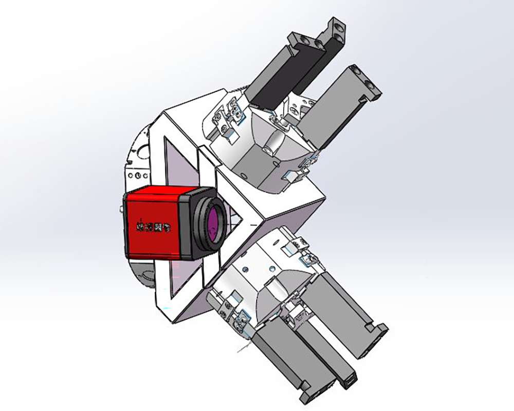
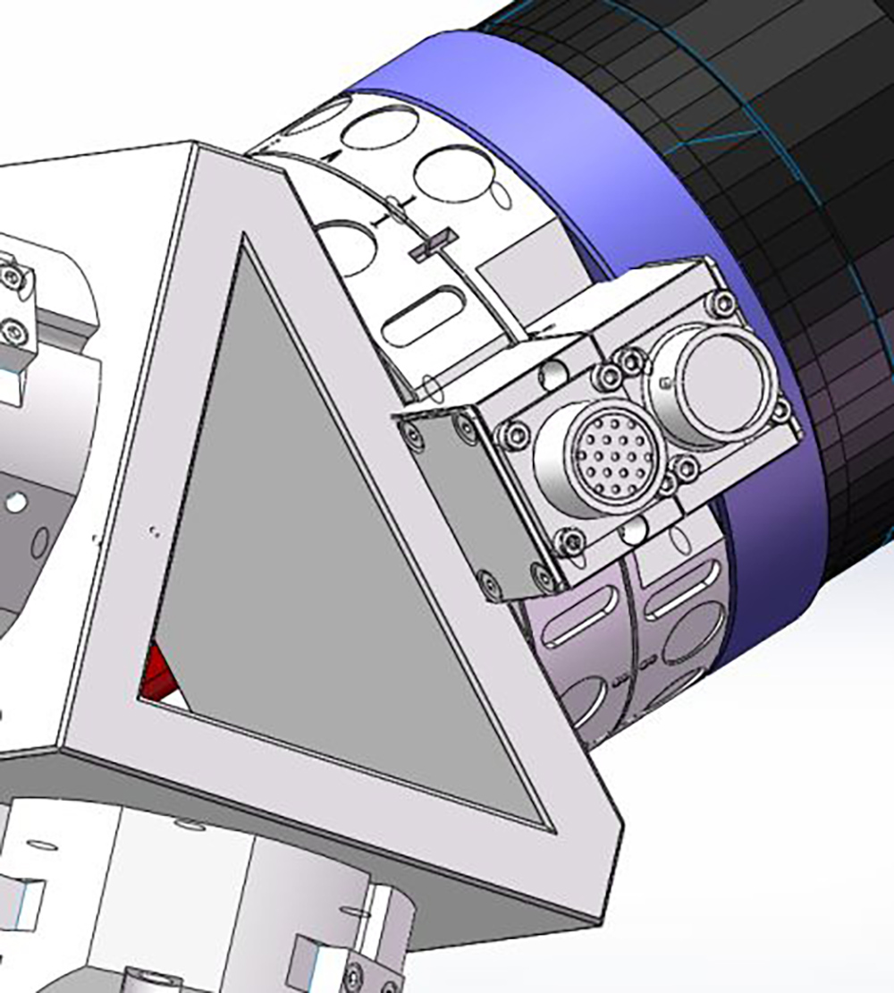
Intelligent robot loading and blanking tong mechanism
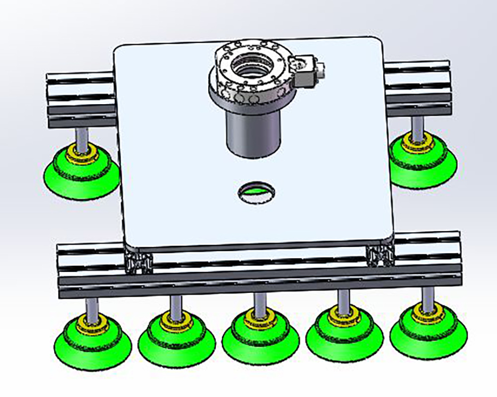
Robot partition plate tong mechanism
Description:
1. Considering the features of this part, we use the three-claw external supporting method to load and blank the materials, which can realize quick turning of the parts in the machine tool;
2. The mechanism is equipped with the position detection sensor and the pressure sensor to detect whether the clamping status and pressure of parts are normal;
3. The mechanism is equipped with a pressurizer, and the workpiece will not fall off in a short time in case of power failure and gas cut-off of main air circuit;
4. Hand changing device is adopted. Changing tong mechanism can quickly complete the clamping of different materials.
Introduction of Tong Changing Device
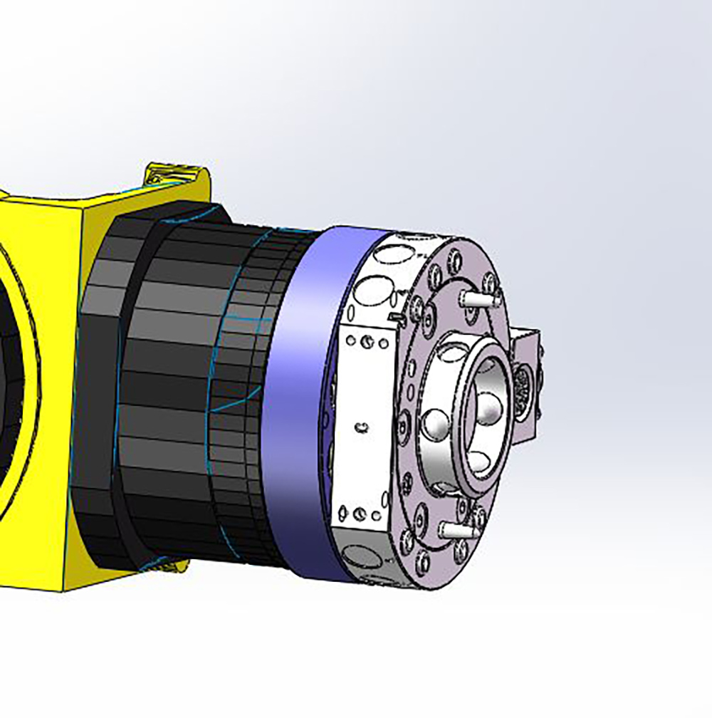
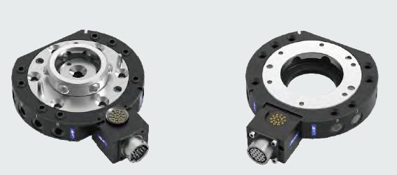
Precise tong changing device is used to quickly change robot tongs, tool ends, and other actuators. Reduce production idle time and increase robot flexibility, featured as:
1. Unlock and tighten air pressure;
2. Various power, liquid and gas modules can be used;
3. Standard configuration can quickly connect with the air source;
4. Special insurance agencies can prevent the risk of accidental gas cut-off;
5. No spring reaction force; 6. Applicable to automation field;
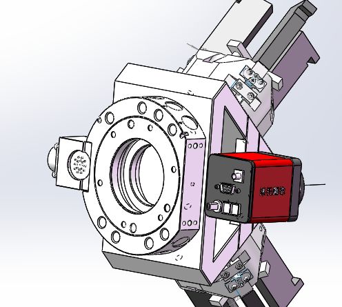
Introduction to Vision System-Industrial Camera
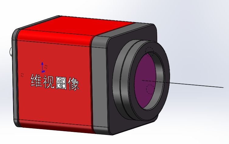
1. The camera adopts high-quality CCD and CMDS chips, which has the characteristics of high resolution ratio, high sensitivity, high signal-to-frequency ratio, wide dynamic range, excellent imaging quality and first-class color restoration capability;
2. Area array camera has two data transmission modes: GIGabit Ethernet (GigE) interface and USB3.0 interface;
3. The camera has compact structure, small appearance, lightweight and installed. High transmission speed, strong anti-interference ability, stable output of high-quality image; It is applicable to code reading, defect detection, DCR and pattern recognition; Color camera has strong color restoration ability, suitable for scenarios with high color recognition requirement;
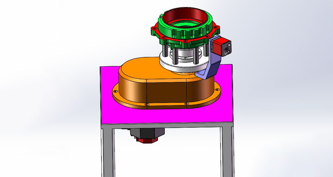
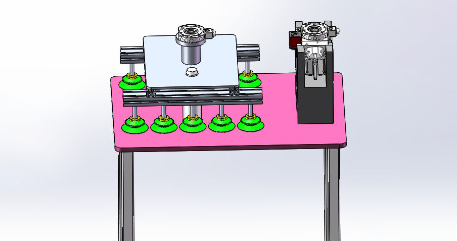
Introduction of Angular Automatic Recognition System
Function Introduction
1. The robot clamps the workpieces from the loading baskets and sends them to the positioning area of the turntable;
2. Turntable rotates under the drive of servo motor;
3. The visual system (industrial camera) works to identify the angular position, and the turntable stops to determine the required angular position;
4. The robot takes out the workpiece and puts another piece in for angular identification;
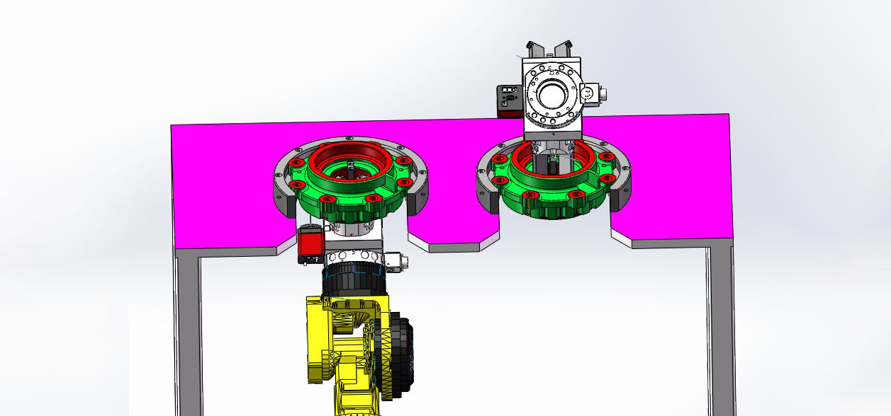
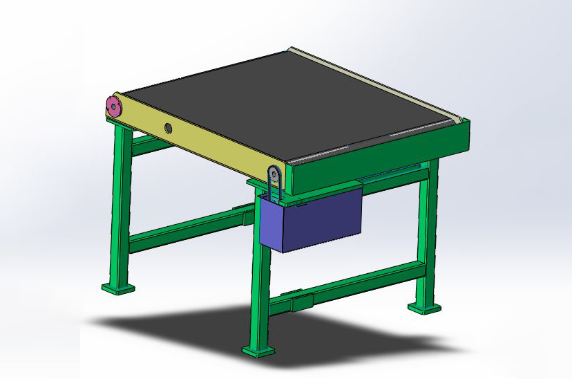
Introduction to Workpiece Roll-over Table
Roll-over station:
1. The robot takes the workpiece and places it at positioning area on the roll-over table (the left station in the figure);
2. The robot grasps the workpiece from the above to realize the rollover of the workpiece;
Robot tong placing table
Function Introduction
1. After each layer of parts are loaded, the layered partition plate shall be placed in the temporary storage basket for the partition plates;
2. The robot can be quickly replaced with suction cup tongs by the tong changing device and remove the partition plates;
3. After the partition plates are well placed, take off the suction cup tong and replace with the pneumatic tong to continue with loading and blanking materials;
Basket for temporary storage of partition plates
Function Introduction
1. A temporary basket for partition plates is designed and planned as the partition plates for loading is withdrawn first and the partition plates for blanking is used later;
2. The loading partition plates are manually placed and are in poor consistency. After the partition plate is put into the temporary storage basket, the robot can take out and place it neatly;
Manual sampling table
Description:
1. Set different manual random sampling frequency for different production stages, which can effectively supervise the effectiveness of online measurement;
2. Instructions for Use: The manipulator will put the workpiece to the set position on the sampling table according to the frequency set manually, and prompt with the red light. The inspector will press the button to transport the workpiece to the safety area outside the protection, take out the workpiece for measurement and store it separately after measurement;
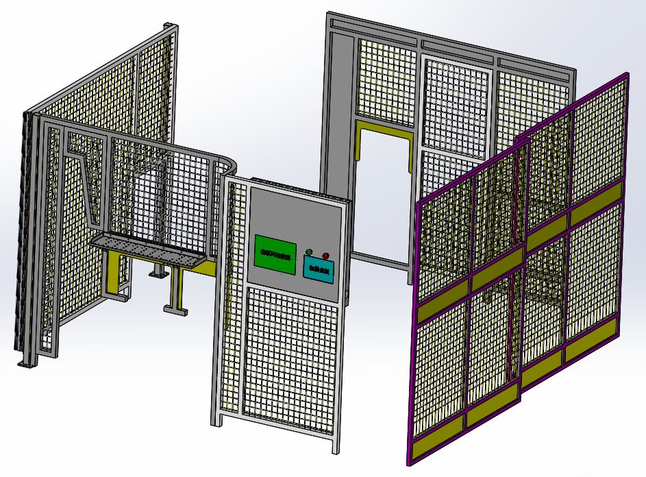
Protective components
It is composed of lightweight aluminum profile (40×40)+mesh (50×50), and the touch screen and emergency stop button can be integrated onto the protective components, integrating safety and aesthetics.
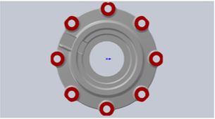
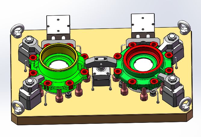
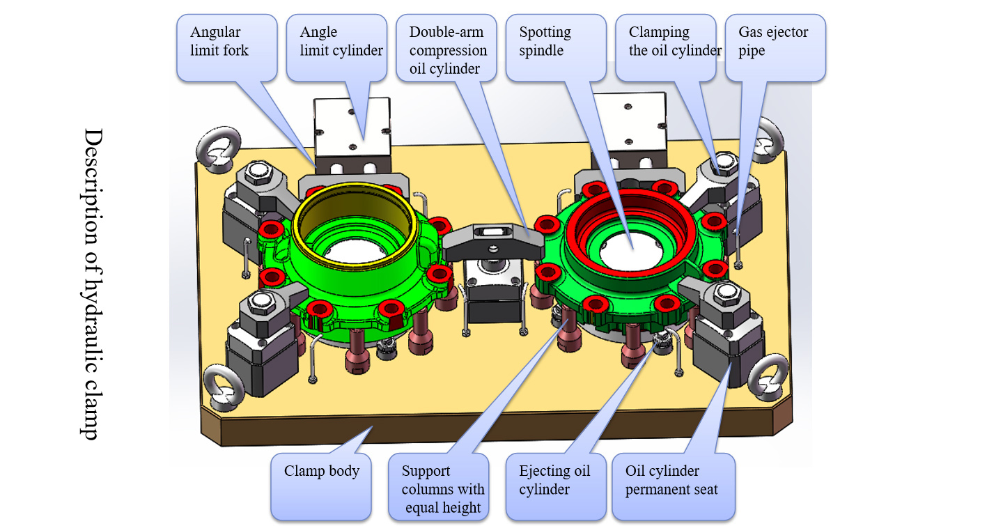
Introduction of OP20 Hydraulic Fixture
Processing Instructions:
1. Take the φ165 inner bore as the base hole, take D datum as the base plane, and take the outer arc of the boss of the two mounting holes as the angular limit;
2. Control the loosening and pressing action of the pressing plate by the command of machine tool M to complete the chamfering processing of the upper plane of mounting hole boss, 8-φ17 mounting hole and both ends of the hole;
3. The fixture has the functions of positioning, automatic clamping, air tightness detection, automatic loosening, automatic ejection, automatic chip flushing and automatic cleaning of positioning datum plane;
Equipment Requirements for Production Line
1. The production line equipment clamp has the functions of automatic clamping and loosening, and realizes automatic clamping and loosening functions under the control of the signals of the manipulator system to cooperate with the loading and blanking action;
2. The skylight position or automatic door module shall be reserved for the metal plate of production line equipment, to coordinate with the electric control signal and manipulator communication of our company;
3. The production line equipment has communication with the manipulator through the connection mode of heavy-load connector (or aviation plug);
4. The production line equipment has an internal (interference) space larger than the safe range of manipulator jaw action;
5. The production line equipment shall ensure that there is no residual iron chips on the positioning surface of the clamp. If necessary, air blowing shall be increased for cleaning (the chuck shall rotate when cleaning);
6. The production line equipment has good chip breaking. If necessary, the auxiliary high-pressure chip breaking device of our company shall be added;
7. When the production line equipment requires accurate stop of the machine tool spindle, add this function and provide corresponding electrical signals;
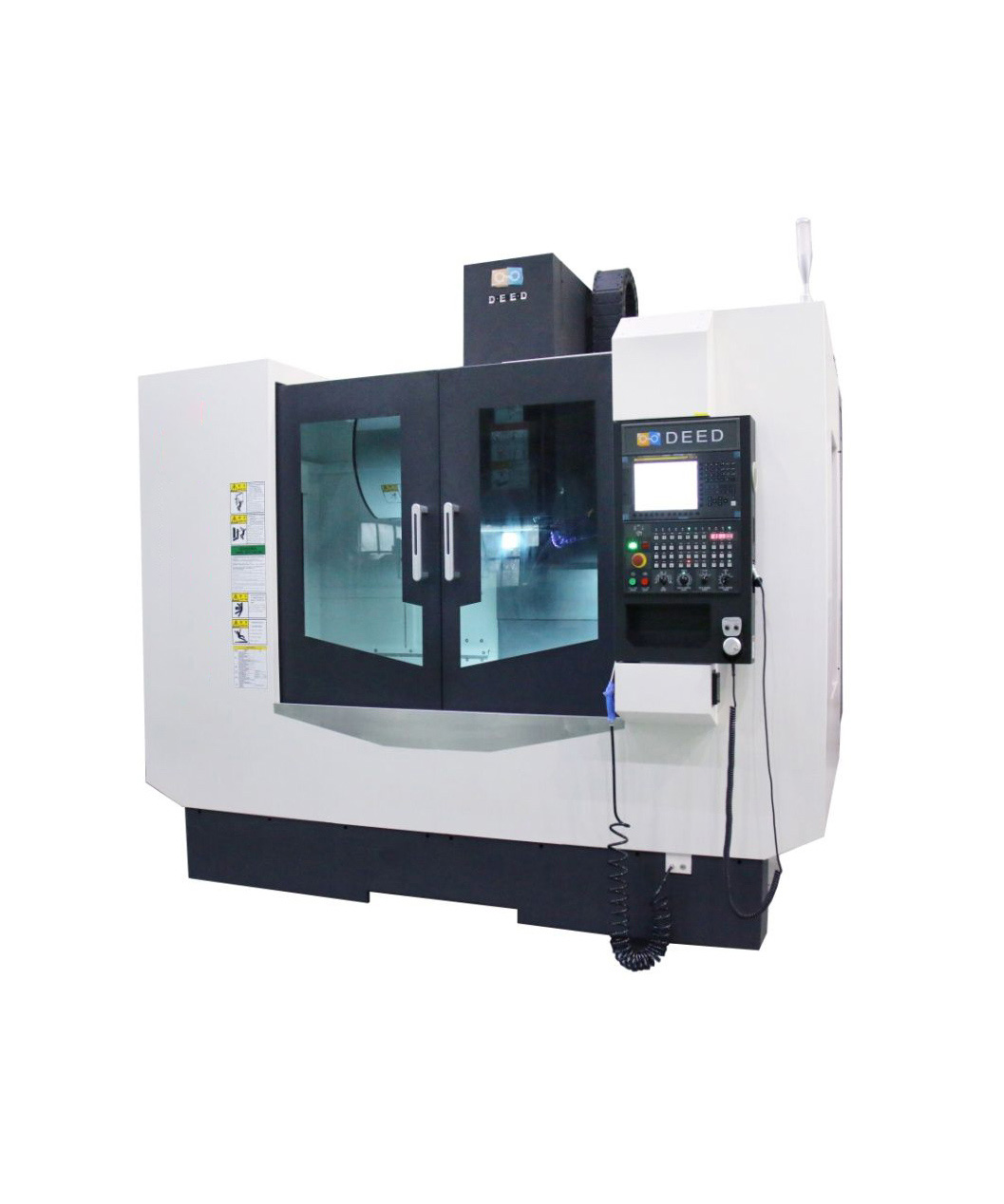
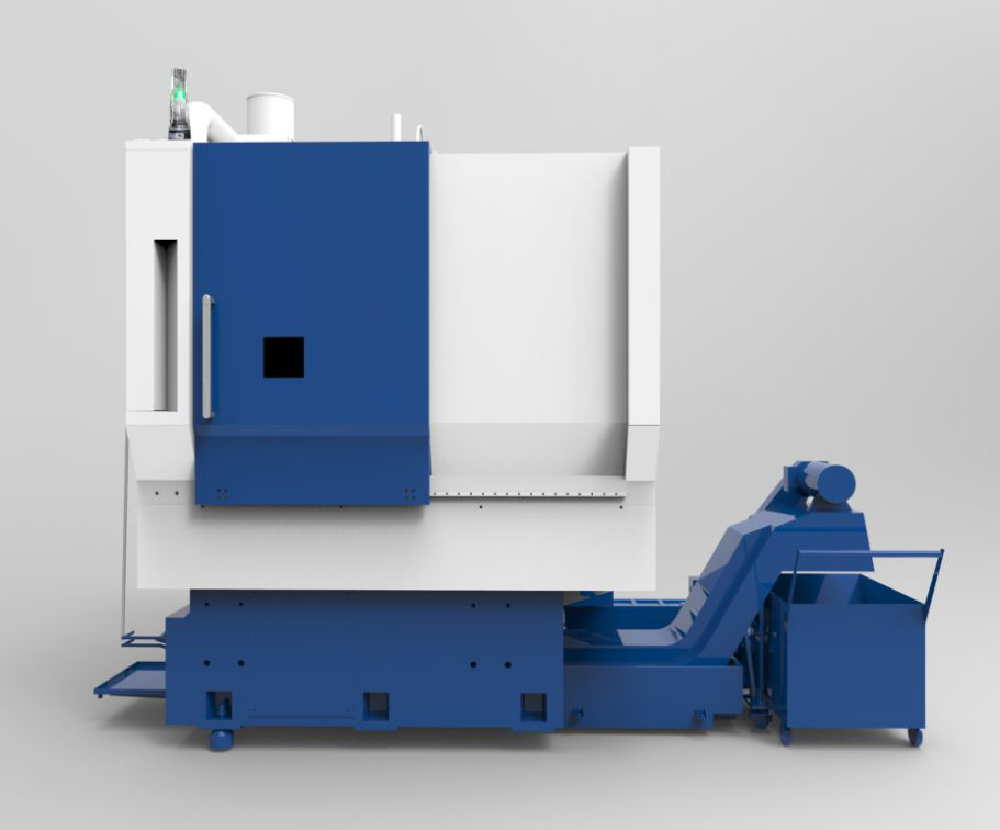
Introduction of Vertical Lathe VTC-W9035
VTC-W9035 NC vertical lathe is suitable for machining rotating parts such as gear blanks, flanges and special-shaped shells, especially suitable for precise, labor-saving and efficient turning of parts such as disks, hubs, brake discs, pump bodies, valve bodies and shells. The machine tool has the advantages of good overall rigidity, high precision, large removal rate of metal per unit time, good accuracy retention, high reliability, easy maintenance, etc. and wide range of applications. Line production, high efficiency and low cost.
| Model type | VTC-W9035 |
| Maximum turning diameter of bed body | Φ900 mm |
| Maximum turning diameter on sliding plate | Φ590 mm |
| Maximum turning diameter of workpiece | Φ850 mm |
| Maximum turning length of workpiece | 700 mm |
| Speed range of spindle | 20-900 r/min |
| System | FANUC 0i - TF |
| Maximum stroke of X/Z axis | 600/800 mm |
| Fast moving speed of X/Z axis | 20/20 m/min |
| Length, width and height of machine tool | 3550*2200*3950 mm |
| Projects | Unit | Parameter | |
| Processing range | X axis travel | mm | 1100 |
| X axis travel | mm | 610 | |
| X axis travel | mm | 610 | |
| Distance from the spindle nose to the workbench | mm | 150~760 | |
| Workbench | Size of workbench | mm | 1200×600 |
| Maximum load of workbench | kg | 1000 | |
| T-groove (size×quantity×spacing) | mm | 18×5×100 | |
| Feeding | Fast feeding speed of X/Y/Z axis | m/min | 36/36/24 |
| Spindle | Driving mode | Belt type | |
| Spindle taper | BT40 | ||
| Maximum operating speed | r/min | 8000 | |
| Power (Rated/Maximum) | KW | 11/18.5 | |
| Torque (Rated/Maximum) | N·m | 52.5/118 | |
| Accuracy | X/Y/Z axis positioning accuracy (half closed loop) | mm | 0.008(total length) |
| X/Y/Z axis repetition accuracy (half closed loop) | mm | 0.005(total length) | |
| Tool magazine | Type | Disc | |
| Tool magazine capacity | 24 | ||
| Maximum tool size (Full tool diameter/empty adjacent tool diameter/length) | mm | Φ78/Φ150/ 300 | |
| Maximum tool weight | kg | 8 | |
| Miscellaneous | Air supply pressure | MPa | 0.65 |
| Power capacity | KVA | 25 | |
| Overall dimension of machine tool (length×width×height) | mm | 2900×2800×3200 | |
| Weight of machine tool | kg | 7000 | |