

Process Analysis of Production Line
Die retrorei im technischen prozess
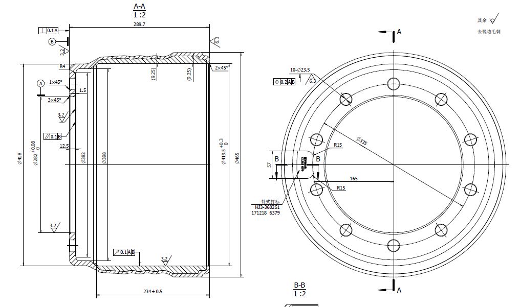
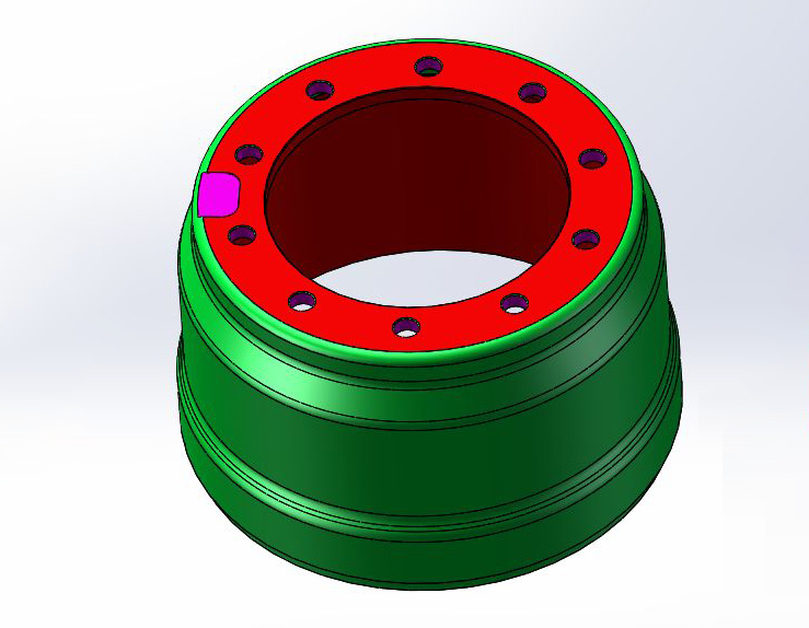
1. The disposable clamping process is adopted during turning. Turning all machining parts, including the bottom surface of the workpieces.
2. During drilling, hydraulic clamps shall be used to locate with the inner diameter of Φ282 and the upper end face, drill 10-Φ23.5 mounting hole and chamfering on both sides, and mill the pneumatic marking area;
Equipment List
|
OP10 machining Cycle timer |
|||||||||||||||
|
Route Description |
|
||||||||||||||
|
Customer |
Workpiece material |
45 |
Model of machine tool |
Archive No. |
|||||||||||
|
Product Name |
Cutting tool shaft welded parts |
Drawing No. |
Date of preparation |
2021.1.19 |
Prepared by |
||||||||||
|
Process step |
Knife No. |
machining content |
Tool Name |
Cutting Diameter |
Cutting speed |
Rotational speed |
Feed per revolution |
feed by machine tool |
Number of cuttings |
Each process |
Machining time |
Idle Time |
Tighten and loosen |
Tool change time |
|
|
No. |
No. |
Desoriptions |
Tools |
D mm |
VcM/min |
R pm |
mm/Rev |
mm/Min |
Times |
Length mm |
Sec |
Sec |
Sec |
||
|
1 |
T01 |
Lathe the upper end face roughly |
455.00 |
450 |
315 |
0.35 |
110 |
1 |
20.0 |
10.89 |
3 |
3 |
|||
|
2 |
T02 |
Lathe roughly DIA 419.5 inner bore, DIA 382 step face and DIA 282 inner bore |
419.00 |
450 |
342 |
0.35 |
120 |
1 |
300.0 |
150.36 |
3 |
3 |
|||
|
3 |
T03 |
Lathe the end face precisely |
455.00 |
450 |
315 |
0.25 |
79 |
1 |
20.0 |
15.24 |
3 |
||||
|
4 |
T04 |
Lathe precisely the DIA 419.5 inner bore, DIA 382 step face and DIA 282 inner bore |
369.00 |
450 |
388 |
0.25 |
97 |
1 |
300. 0 |
185.39 |
|||||
|
5 |
T05 |
Lathe reversely and roughly the lower end face |
390.00 |
420 |
343 |
0.35 |
120 |
1 |
65.0 |
32.49 |
3 |
||||
|
6 |
T06 |
Lathe reversely and precisely the lower end face |
390.00 |
450 |
367 |
0.25 |
92 |
1 |
65.0 |
42.45 |
3 |
||||
|
Description: |
Cutting time: |
437 |
Second |
Time for clamping with fixture and for loading and blanking materials: |
15.00 |
Second |
|||||||||
|
Auxiliary time: |
21 |
Second |
Total machining man-hours: |
472.81 |
Second |
||||||||||
|
OP20 machining Cycle timer |
|||||||||||||||
|
Route Description |
 |
||||||||||||||
|
Customer |
Workpiece material |
HT250 |
Model of machine tool |
Archive No. |
|||||||||||
|
Product Name |
Brake drum |
Drawing No. |
Date of preparation |
2021.1.19 |
Prepared by |
||||||||||
|
Process step |
Knife No. |
machining content |
Tool Name |
Cutting Diameter |
Cutting speed |
Rotational speed |
Feed per revolution |
feed by machine tool |
Number of cuttings |
Each process |
Machining time |
Idle Time |
Tighten and loosen |
Tool change time |
|
|
No. |
No. |
Desoriptions |
Tools |
D mm |
VcM/min |
R pm |
mm/Rev |
mm/Min |
Times |
Length mm |
Sec |
Sec |
Sec |
||
|
1 |
T01 |
Drill 10-DIA 23.5 mounting hole |
Down-the-hole drill DIA 23.5 |
23.50 |
150 |
2033 |
0.15 |
305 |
10 |
15.0 |
29.52 |
20 |
5 |
||
|
2 |
T04 |
10-DIA 23 Orifice Chamfering |
DIA 30 compound reaming chamfering cutter |
30.00 |
150 |
1592 |
0.20 |
318 |
10 |
3.0 |
6.65 |
20 |
5 |
||
|
3 |
T06 |
10-DIA 23.5 Back orifice chamfering |
DIA 22 reverse chamfering cutter |
22.00 |
150 |
2171 |
0.20 |
434 |
10 |
3.0 |
4.14 |
40 |
5 |
||
|
4 |
T08 |
Milling Marking Area |
DIA 30 square shoulder milling |
30.00 |
80 |
849 |
0.15 |
127 |
1 |
90.0 |
42.39 |
4 |
5 |
||
|
Description: |
Cutting time: |
82 |
Second |
Time for clamping with fixture and for loading and blanking materials: |
30 |
Second |
|||||||||
|
Auxiliary time: |
104 |
Second |
Total machining man-hours: |
233.00 |
Second |
||||||||||
Introduction to Production Line
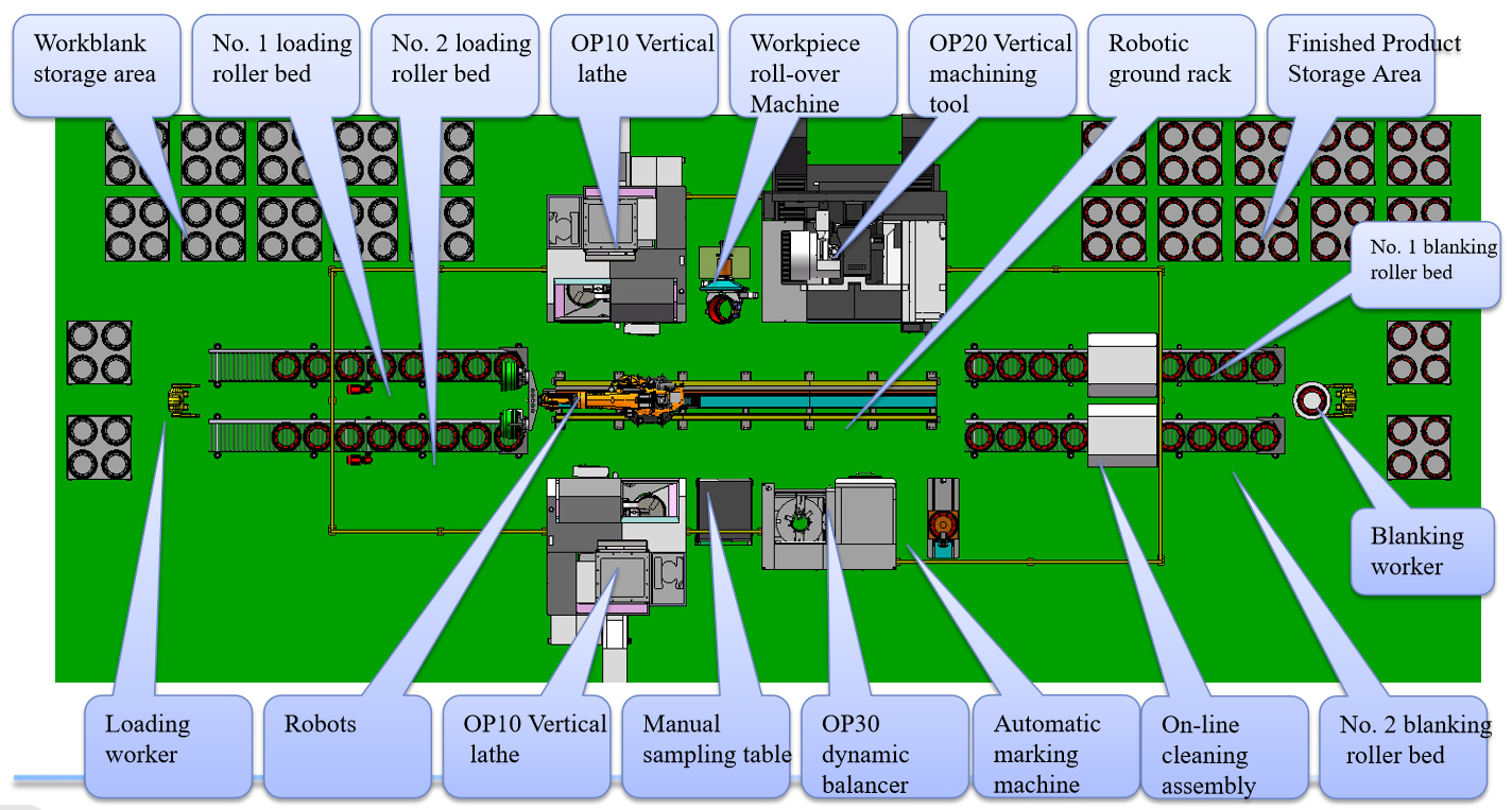
Layout of Production Line
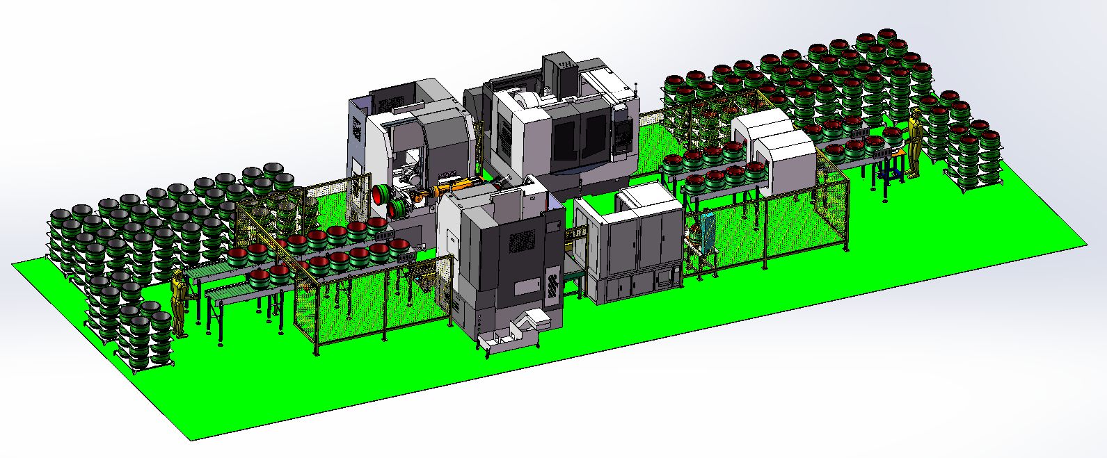
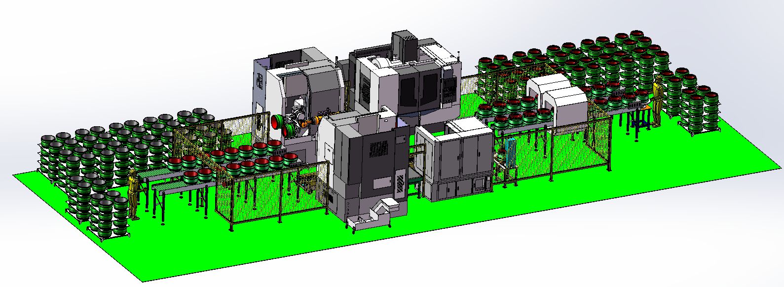
Introduction to Production Line
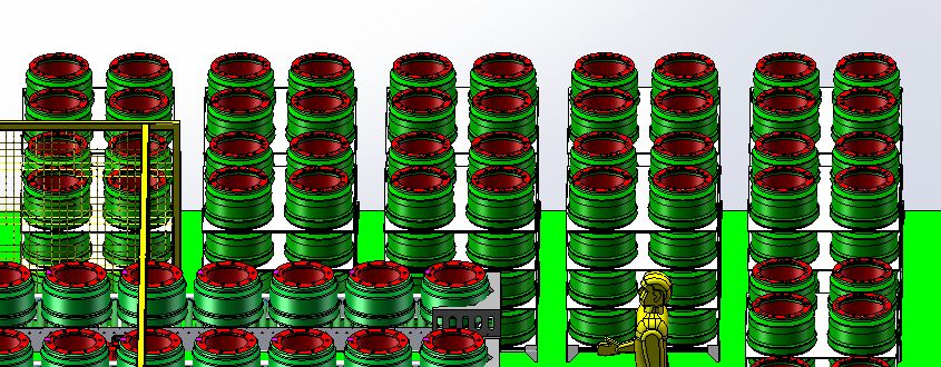
The production line consists of 1 loading unit, 1 lathe machining unit and 1 blanking unit. Robots transport materials between the stations within each unit. Forklifts place baskets in front of the loading and blanking units; The production line covers an area of: 22.5m×9m
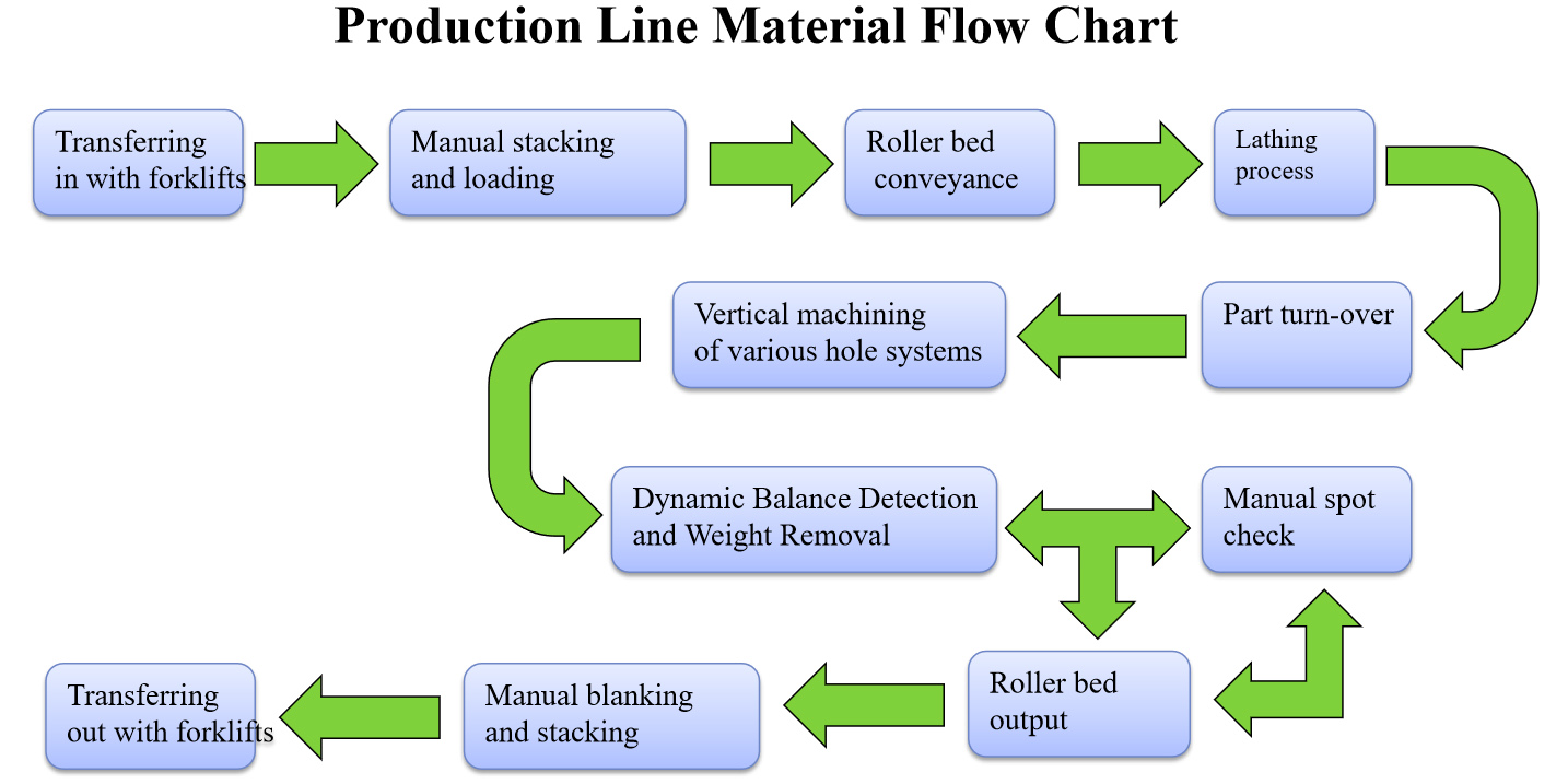
Description of production line
1. The work blanks are transported to loading stations by forklifts, hoisted manually to the roller bed, and sent to the loading stations through the rollers. The loading and unloading of the balancing machine in the lathe process, the roll-over process and the drilling and milling process are completed by robots. The finished products are sent to the blanking stations through the roller bed, and sent out by the forklifts after manually hoisting and stacking;
2. Large-scale electronic display screens shall be set on the logistics transmission lines to update and display the information of output, defective products and safety production days in real time;
3. The transmission line shall be provided with warning light at each unit, which can display information such as being normal, being lack of material and alarming;
4. Automatic line adopts processing unit mode and multi-unit wiring mode, with flexible layout, suitable for different layout requirements of customers;
5. Adopt joint robot for loading and blanking, which has high stability, convenient maintenance and long service life;
6. Small demand for personnel. The daily personnel demand for each shift of this automatic line are as follows:
Forkliftman 1~2 persons (in charge of lifting, forklifting and transferring work blanks/finished products)
Maintenance Engineer 1 person (in charge of routine maintenance-oil and water cutters, etc.)
7. The automatic line has strong extensibility. Such as mixed wire machining, workpiece traceability and other functions, with low expansion cost;
Loading unit
1. The loading roller bed line can store 12×16=192 pieces; 2. Manually open the stack and hoist it to the loading roller bed and send it to the loading station by the roller conveyor; 3. After opening the stack, the empty tray shall be clamped and placed on the blanking line of empty trays, stacking into 8 layers, and the empty tray stacking shall be removed manually and placed in the storage area;1. The loading roller bed line can store 12×16=192 pieces;
2. Manually open the stack and hoist it to the loading roller bed and send it to the loading station by the roller conveyor;
3. After opening the stack, the empty tray shall be clamped and placed on the blanking line of empty trays, stacking into 8 layers, and the empty tray stacking shall be removed manually and placed in the storage area;
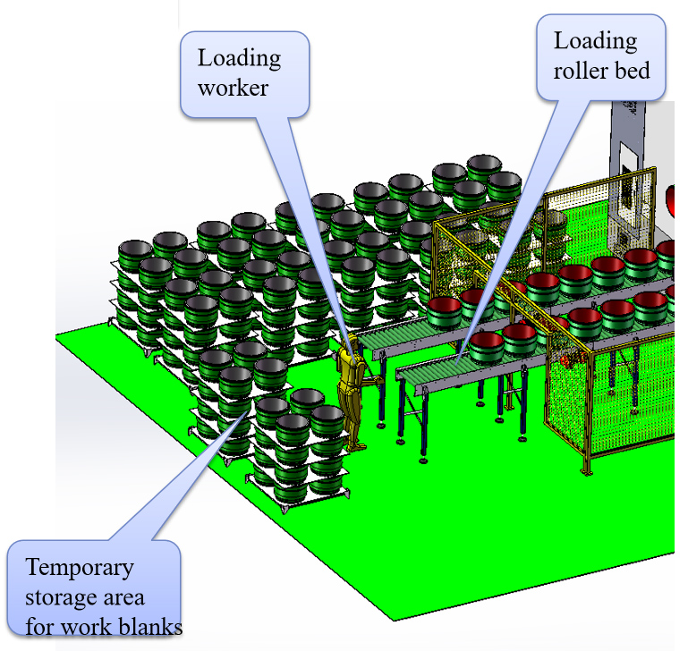
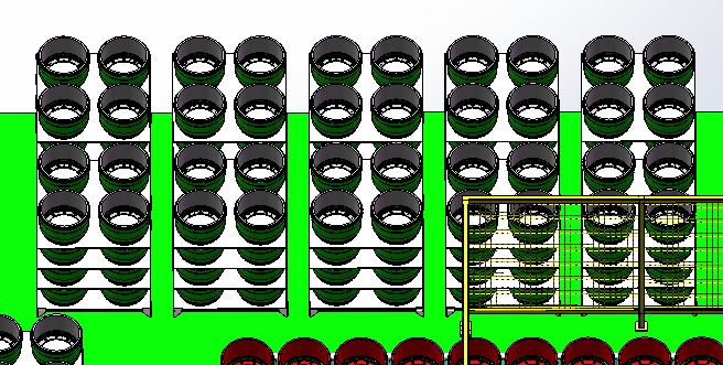

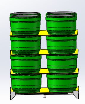
Introduction to work blank stacks
1. One stack of 16 pieces and 4 layers in total, with partition plates between each layer;
2. The work blank stack can store 160 pieces;
3. The pallet is suggested to be prepared by the customer. Requirement: (1) Good rigidity and flatness (2) being able to be clamped by the robot.
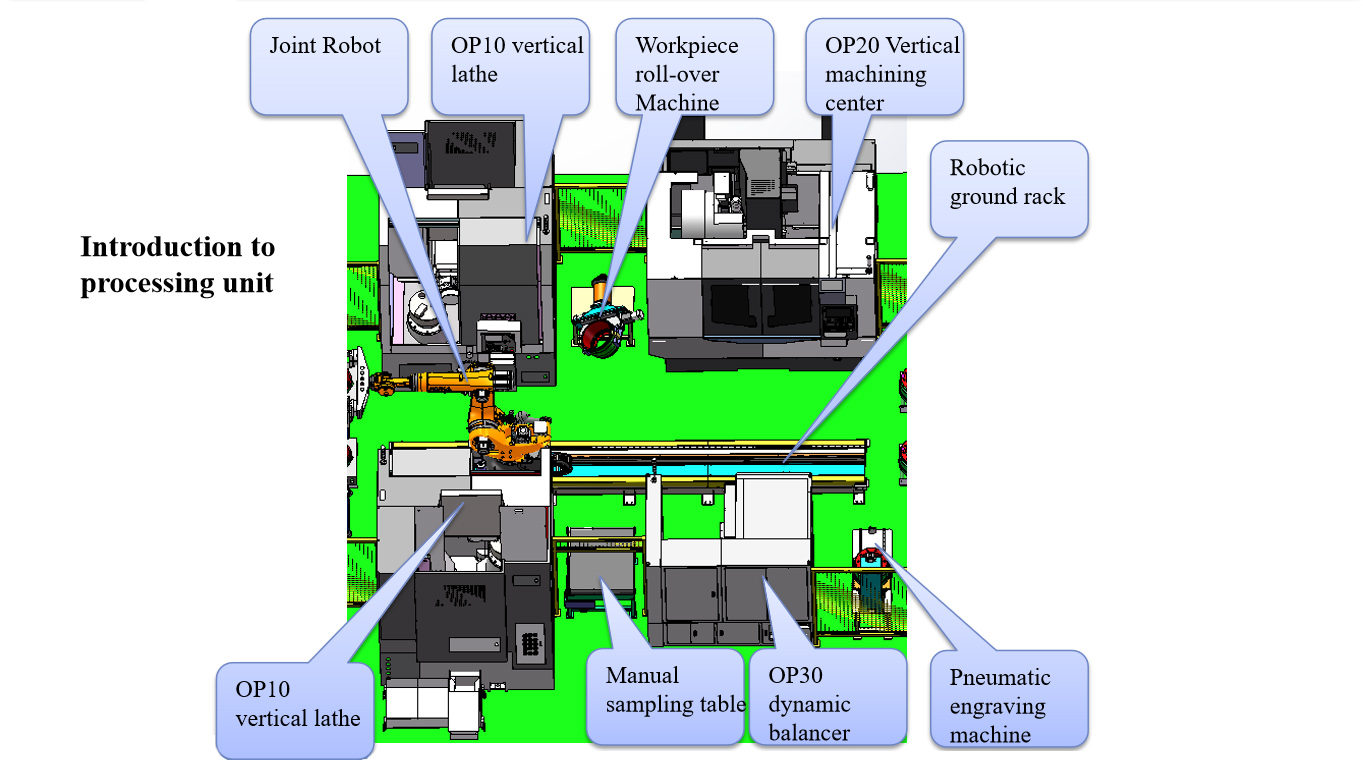
Introduction to processing unit
1. The lathing process consists of two vertical lathes, No. 1 robot and the robot ground rack, which undertakes the machining of outer circle, inner hole step surface and end face of the part;
2. Roll-over station consists of 1 rolling over machine, which undertakes automatic rolling over of parts;
3. The drilling and milling process consists of 1 vertical machining center and one No. 2 robot, which undertakes the machining of the installation hole and marking area of this part.
4. The dynamic balancing and weight removing process consists of a vertical dynamic balancer, which undertakes the dynamic balancing detection and weight removing of the parts;
5. The manual spot check station consists of a belt conveyor, which undertakes the transport of the spot checked parts and is used as the inspection platform;
6. The working station of the pneumatic engraving machine undertakes the work of engraving and marking all products;
Introduction of the blanking unit
1. The loading roller bed line can store 12×16=192 pieces;
2. The trays and partition plates at the loading station are transported to the blanking area by the forklifts;
3. The finished products are transported to the blanking station by the roller conveyor, and are hoisted and stacked manually and transferred with forklifts;
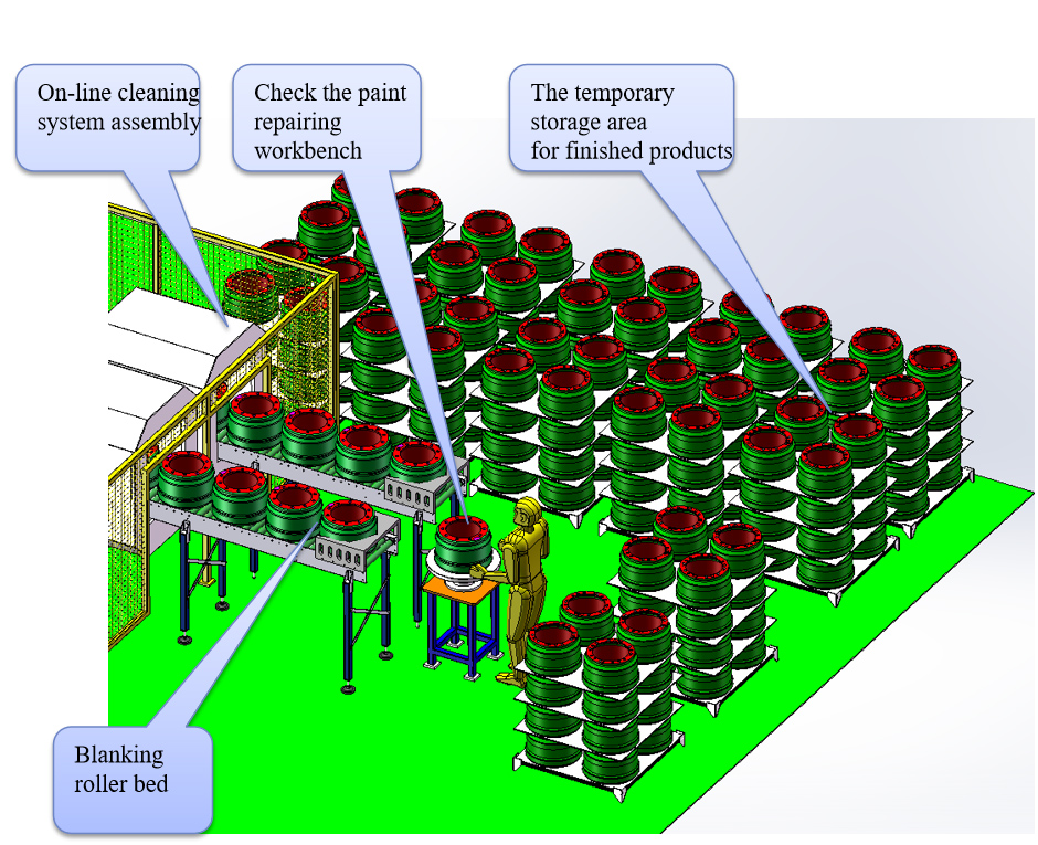
Introduction of finished product stacking
1. One stack of 16 pieces and 4 layers in total, with partition plates between each layer;
2.192 pieces can be stored in the stack of finished products;
3. The pallet is suggested to be prepared by the customer. Requirement: (1) Good rigidity and flatness (2) being able to be clamped by the robot.
Introduction of main functional components of the production line
Introduction to Machining and Dynamic Balancing Weight Removal Unit Robot
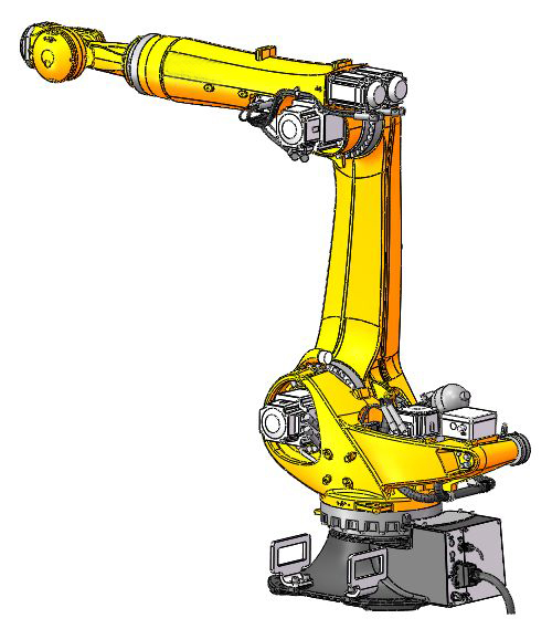
Chenxuan robot: SDCX-RB08A3-1700
| Basic data | |
| Type | SDCX-RB08A3-1700 |
| Number of axes | 6 |
| Maximum coverage | 3100mm |
| Pose repeatability (ISO 9283) | ±0.05mm |
| Weight | 1134kg |
| Protection classificationof the robot | Protection rating,IP65 / IP67in-line wrist(IEC 60529) |
| Mounting position | Ceiling, permissible angle of inclination ≤ 0º |
| Surface finish, paintwork | Base frame: black (RAL 9005) |
| Ambient temperature | |
| Operation | 283 K to 328 K (0 °C to +55 °C) |
| Storage and transportation | 233 K to 333 K (-40 °C to +60 °C) |
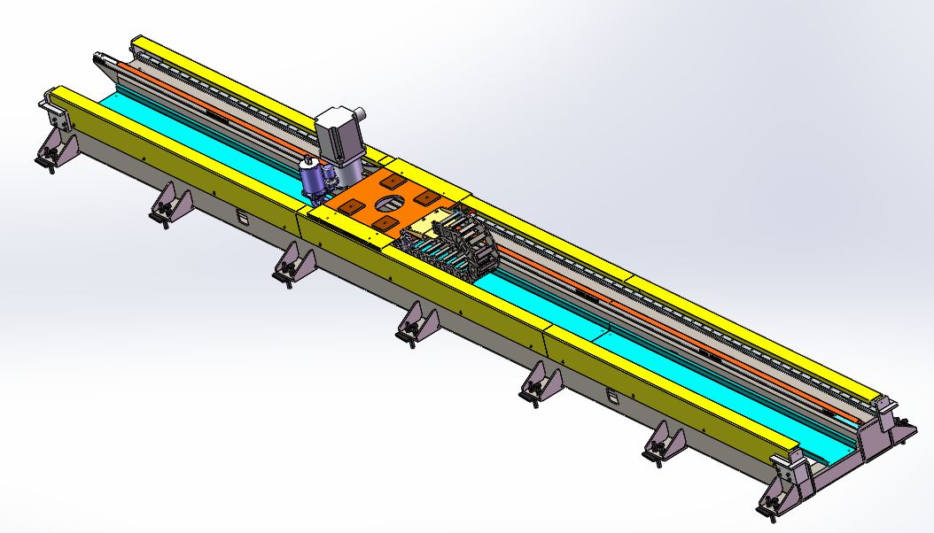
Introduction of Robot Travel Axis
The structure is composed of a joint robot, a servo motor drive and a pinion and rack drive, so that the robot can make rectilinear motion back and forth. It realizes the function of one robot serving multiple machine tools and gripping workpieces at several stations and can increase the working coverage of joint robots;
Traveling track applies the base welded with steel pipes and is driven by servo motor, pinion and rack drive, to increase the working coverage of the joint robot and effectively improve the utilization rate of robot;
The traveling track is installed on the ground;
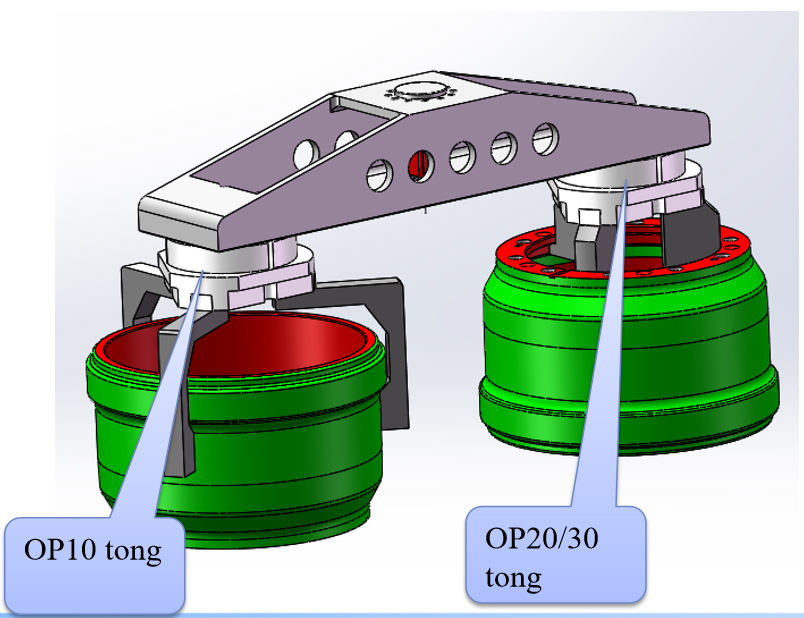
Introduction of tongs of loading and blanking robots
Description:
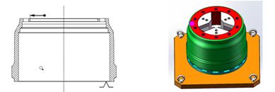
1. As per the characteristics of this part, we adopt three-claw external wave surface;
2. The mechanism is equipped with the position detection sensor and the pressure sensor to detect whether the clamping status and pressure of parts are normal;
3. The mechanism is equipped with a pressurizer, and the workpiece will not fall off in a short time in case of power failure and gas cut-off of main air circuit;
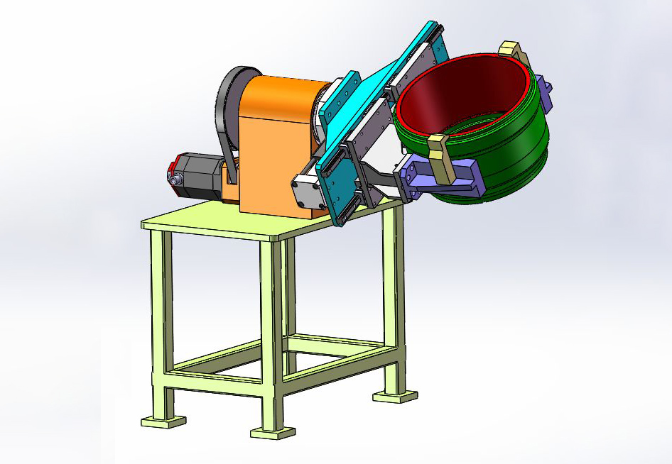
Introduction of Automatic Roll-over Machine
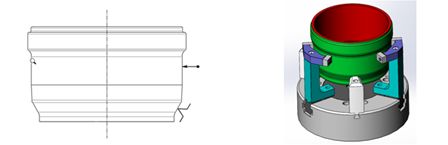
Description:
The mechanism is composed of a fixed frame, a support base assembly and a pneumatic tong assembly. It has anti-loose and anti-dropping function after air cutoff, and can realize 180°roll over of line workpieces;
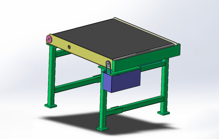
Introduction to manual spot check bench
Description:
1. Set different manual random sampling frequency for different production stages, which can effectively supervise the effectiveness of online measurement;
2. Instructions for Use: The manipulator will put the workpiece to the set position on the spot check bench according to the frequency set manually, and prompt with the red light. The inspector will press the button to transport the workpiece to the safety area outside the protection, take out the workpiece for measurement and return it to the roller bed after measurement;
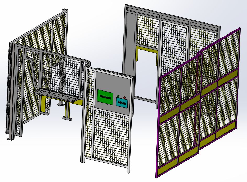
Protective components
It is composed of lightweight aluminum profile (40×40)+mesh (50×50), and the touch screen and emergency stop button can be integrated onto the protective components, integrating safety and aesthetics.
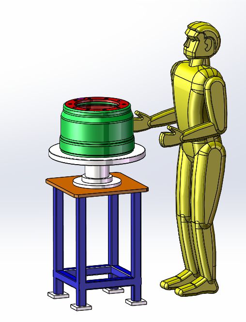
Introduction to the Inspection Station for paint repairing
Description:
The mechanism is composed of a fixed frame and a turntable. The staff lift the finished products to the turntable, rotate the turntable, check whether there are bumps, scratches and other phenomena, and timely repair the bumping defects and the paint surface;


