

Project Requirements
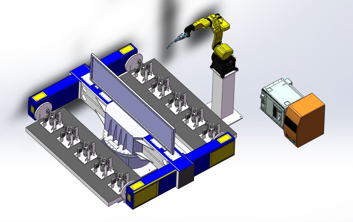
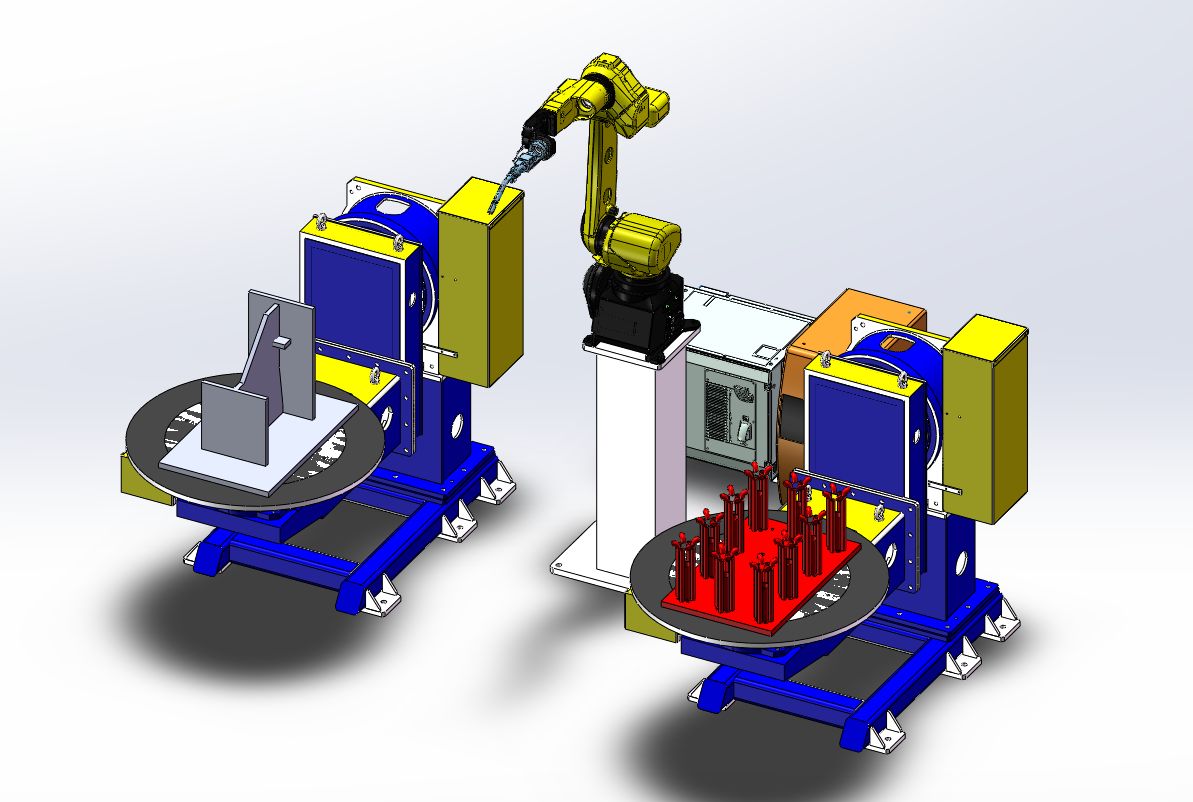
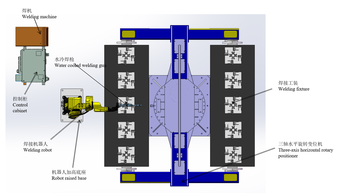
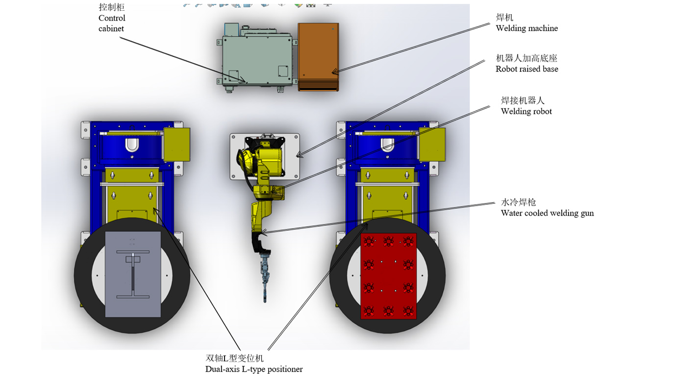
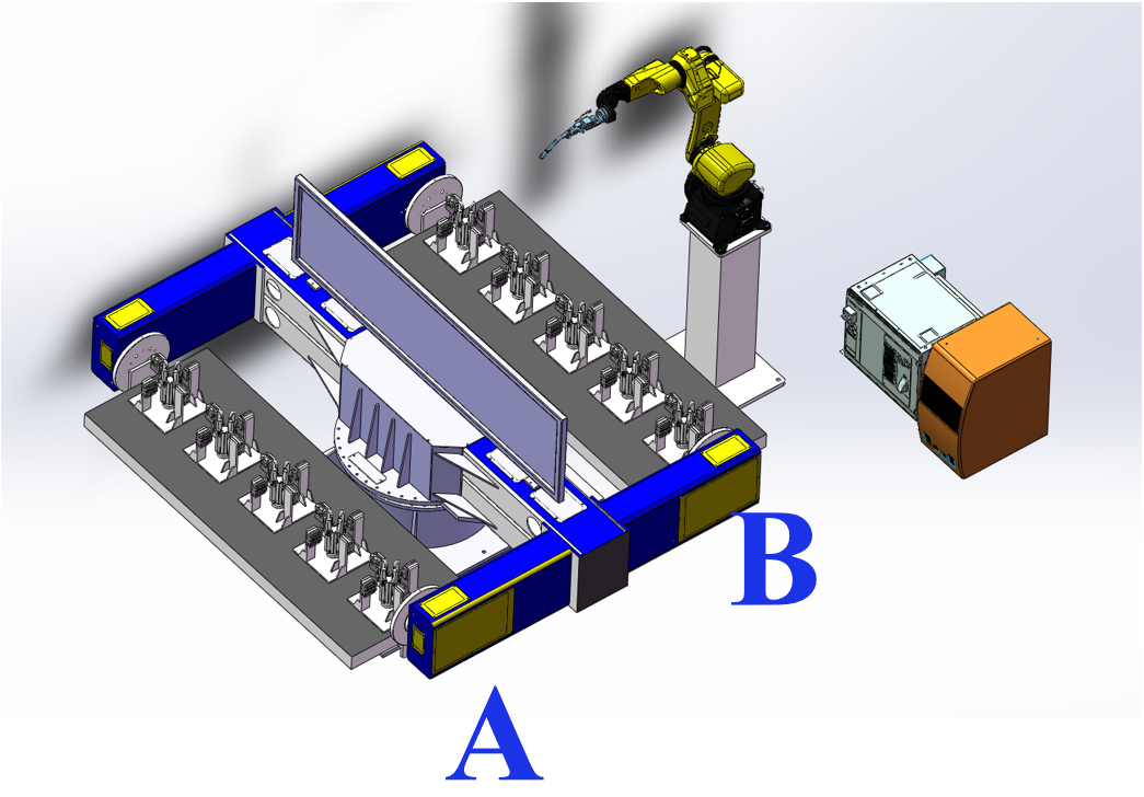
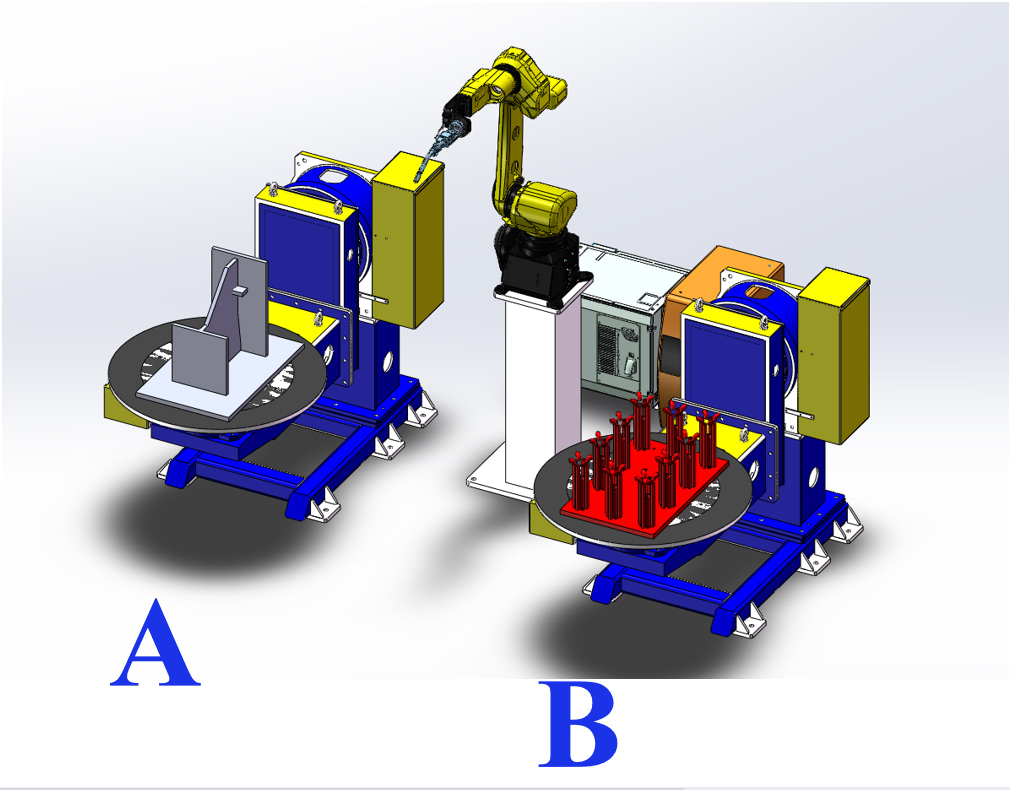
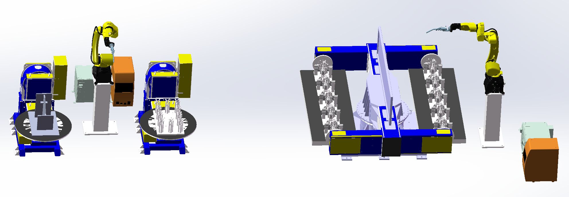
Overall Layout&3D Model

Note: The scheme diagram is only used for layout illustration and does not represent the physical structure of equipment. The specific size shall be determined according to the customer’s site conditions.
Workpiece physical drawing&3D model
Workpiece physical drawing & 3D model
Scheme Layout
Workflow
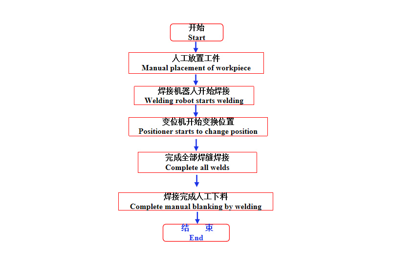
Conditions for workstation operation
(1) Manually place the workpiece in the positioner and fix it according to requirements.
(2) After all devices are powered on and no alarm is displayed, get ready for installation.
(3) The robot stops at the work origin, and the running program of the robot is the corresponding production program.
Welding process of sleeve subassembly
1. Manually install five sets of sleeve parts on side A.
2. Return to safety area manually and start button clamp cylinder to tighten workpiece.
3. The positioner rotates until the robot on side B starts welding.
4. Manually take down the workpieces welded on side A, and then five sets of drum parts.
5. Cycle the operation of the above links.
The welding time for each set of sleeves is 3min (including installation time), and the welding time of 10 sets is 30min.
Welding process of embedded plate assembly + sleeve assembly
1. Manually install the pre-pointed embedded plate on the L-type positioner on side A.
2. Start button robot welding embedded plate assembly (15min/set). 3.
3. Manually install the loose parts of the sleeve assembly on the L-type positioner on side B.
4. The robot continue to weld the sleeve assembly after welding the embedded plate assembly(sleeve welding for 10min+manual installation of workpiece and robot spot welding for 5min)
5. Remove the embedded plate assembly manually.
6. Manual welding of embedded plate assembly (removing-spot welding-loading within 15min)
7. Manually install the pre-pointed embedded plate on the L-type positioner on side A.
8. Remove the welded sleeve assembly and install the spare parts
9. Cycle the operation of the above links.
Welding completion time of embedded plate is 15min+welding completion time of sleeve assembly is 15min.
Total time 30min
Introduction of Tong Changing Device
The welding time of the robot at the above-mentioned beat is the most sufficient without stopping. According to 8 hours per day and two operators, the output of two assemblies totals 32 sets per day.
To increase the output:
One robot is added to the three-axis positioner at the sleeve subassembly station and changed to double machine welding. At the same time, the embedded plate assembly+ sleeve assembly station also need to add two sets of L-type positioner and one set of robot. On a 8-hour day and three operators basis, the output of two assemblies totals 64 sets per day.
Equipment List
| Item | S/N | Name | Qty. | REMARKS |
| Robots | 1 | RH06A3-1490 | 2 sets | Provided by Chen Xuan |
| 2 | Robot control cabinet | 2 sets | ||
| 3 | Robot raised base | 2 sets | ||
| 4 | Water cooled welding gun | 2 sets | ||
| Peripheral equipment | 5 | Welding Power Source MAG-500 | 2 sets | Provided by Chen Xuan |
| 6 | Dual-axis L-type positioner | 2 sets | ||
| 7 | Three-axis horizontal rotary positioner | 1 set | Provided by Chen Xuan | |
| 8 | Fixture | 1 set | ||
| 9 | Gun Cleaner | Set | Optional | |
| 10 | Dust removing equipment | 2 sets | ||
| 11 | Safety fence | 2 sets | ||
| Related Service | 12 | Installation and commissioning | 1 item | |
| 13 | Packaging and Transportation | 1 item | ||
| 14 | Technical training | 1 item |
Technical Specification
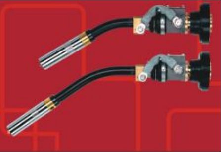
Built-in water-cooled welding gun
1) Each welding gun shall go through ternary measurement to ensure the dimensional accuracy;
2) The R part of welding gun is made by wet wax casting method, which will not be deformed due to high temperature generated by welding;
3) Even if the welding gun collides with the workpiece and fixture during operation, the welding gun will not bend and no re-correction is required;
4) Improve the rectifier effect of shielding gas;
5) The accuracy of single barrel is within 0.05;
6) The picture is for reference only, and it’s subject to final choice.
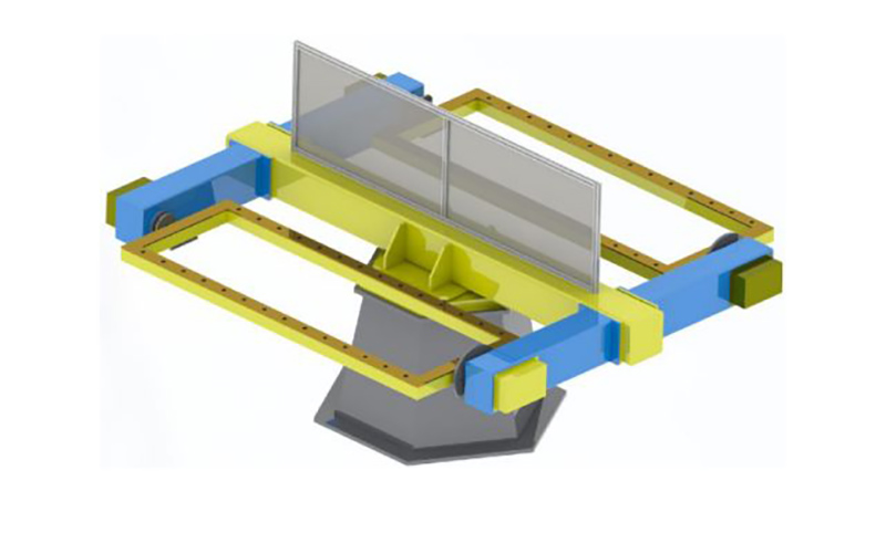
Dual-axis L-type positioner
Positioner is special welding auxiliary equipment, which is suitable for welding displacement of rotary work, so as to obtain ideal machining position and welding speed. It can be used with manipulator and welding machine to form an automatic welding center, and can also be used for workpiece displacement during manual operation. Variable output with variable-frequency drive is adopted for workbench rotation, with high precision of speed regulation. Remote control box can realize remote operation of workbench, and can also be connected with manipulator and welding machine control system to realize linked operation. The welding positioner is generally composed of the rotary mechanism and turnover mechanism of the workbench. The workpiece fixed on the workbench can reach the required welding and assembly angle through lifting, turning and rotation of the workbench. The workbench rotates into variable frequency stepless speed regulation, which can obtain satisfactory welding speed.
Pictures are for reference only, and it’s subject to final design.
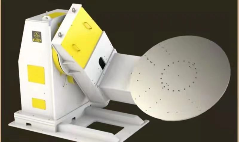
Three-axis horizontal rotary positioner
1) Three-axis horizontal rotary positioner is mainly composed of an integral fixed base, rotary spindle box and tail box, welding frame, servo motor and precision reducer, conductive mechanism, protective cover and electrical control system, etc.
2) By configuring different servo motors, the positioner can be operated remotely through the robot instructor or external operation box;
3) The required welding and assembly angle is achieved by turning the workpiece fixed on the workbench;
4) The rotation of the workbench is controlled by a servo motor, which can achieve ideal welding speed;
5) Pictures are for reference only, and it’s subject to final design;
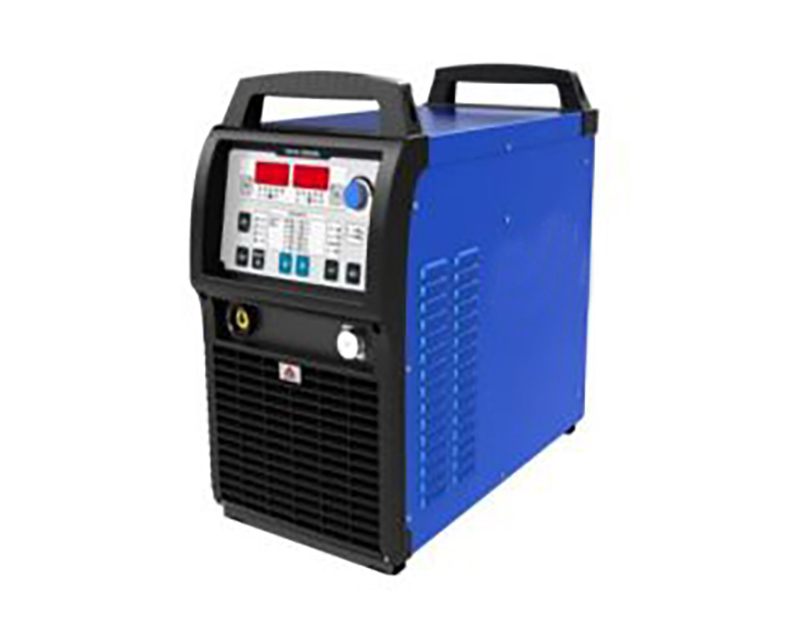
Welding power supply
It is suitable for splicing, lapping, corner joint, tube plate butt joint, intersection line connection and other joint forms, and can realize all position welding.
Safety and reliability
The welding machine and wire feeder are equipped with over-current, over-voltage and over-temperature protection. They have passed the EMC and electrical performance test required by national standard GB/T 15579, and passed the 3C certification to ensure the reliability and safety in use.
Energy conservation and environmental protection
The gas detection time, advance gas supply time and lag gas supply time are adjustable to ensure the reasonable use of gas. When the welding machine is powered on, if it does not enter the welding state within 2 minutes (time adjustable), it will automatically enter the sleep state. Turn off the fan and reduce the energy consumption.
The picture is for reference only, and it’s subject to final choice.
Welding power supply
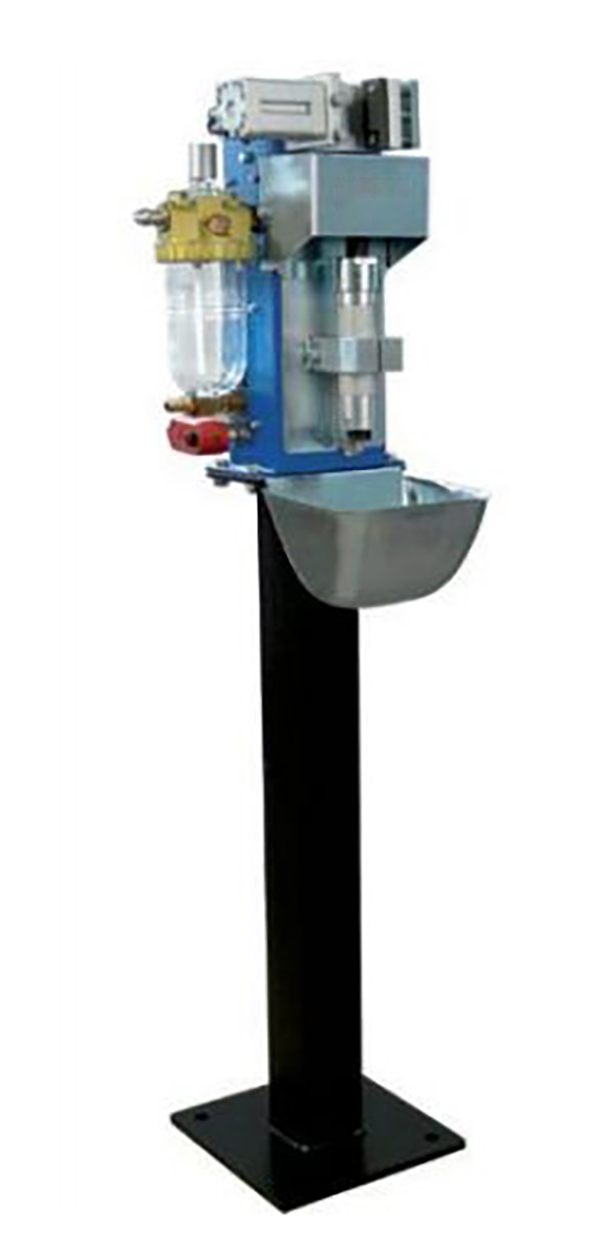
Gun cleaning and silicone oil spraying device and wire cutting device
1) Silicone oil spraying device of the gun cleaning station adopts double nozzle for cross spraying, so that silicone oil can reach the inner surface of welding torch nozzle better and ensure that the welding slag will not adhere to the nozzle.
2) The gun cleaning and silicone oil spraying devices are designed at the same position, and the robot can complete the process of silicone oil spraying and gun cleaning with only one action.
3) In terms of control, the gun cleaning and silicone oil spraying device only needs a start signal, and it can be started according to the specified action sequence.
4) The wire cutting device adopts the self-triggering structure of welding gun, which eliminates the need to use the solenoid valves to control it and simplifies the electrical larrangement.
5) The wire cutting device can be installed separately or installed on the gun cleaning and silicone oil spraying device to form an integrated device, which not only saves installation space, but also makes the arrangement and control of gas path very simple.
6) The picture is for reference only, and it’s subject to final choice.
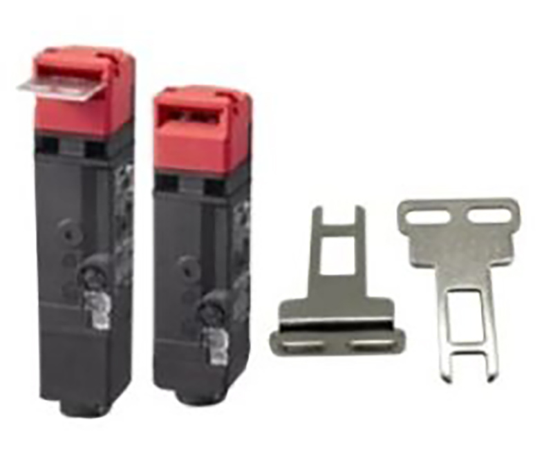
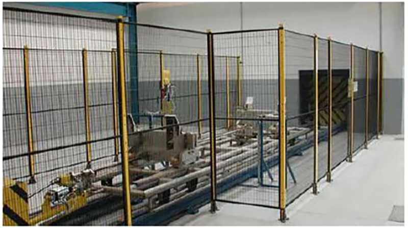
Security fence
1. Set protective fences, safety doors or safety gratings, safety locks and other devices, and conduct necessary interlocking protection.
2. Safety door shall be set at proper position of the protective fence. All doors shall be equipped with safety switches and buttons, reset button and emergency stop button.
3. The safety door is interlocked with the system through safety lock (switch). When the safety door is opened abnormally, the system stops operation and gives an alarm.
4. Safety protection measures guarantee the safety of personnel and equipment through hardware and software.
5. The safety fence can be provided by Party A itself. It is recommended to use high-quality grid welding and bake yellow warning paint on the surface.
Electrical Control System
1. Includes system control and signal communication between equipment, including sensors, cables, slots, switches, etc.;
2. The automatic unit is designed with three-color alarm light. During normal operation, the three-color light displays green; if the unit fails, the three-color light will display red alarm in time;
3. There are emergency stop buttons on the robot control cabinet and teaching box. In case of emergency, the emergency stop button can be pressed to realize the emergency stop of the system and send out an alarm signal at the same time;
4. A variety of application programs can be compiled through the teaching device, many applications can be compiled, which can meet the requirements of product upgrading and new products;
5. All emergency stop signals of the whole control system and safety interlock signals between processing equipment and robots are connected to the safety system and interlocked through the control program;
6. The control system realizes the signal connection between the operating equipment such as robot, loading bin, gripper and machining tools.
7. Machine tool system needs to realize signal exchange with robot system.
Operating environment (provided by Party A)
| Power supply | Power supply: three-phase four-wire AC380V±10%, voltage fluctuation range ±10%, frequency: 50Hz;
The power supply of robot control cabinet is required to be equipped with independent air switch; Robot control cabinet must be grounded with grounding resistance less than 10Ω; The effective distance between the power supply and the robot electric control cabinet is within 5 meters. |
| Air source | The compressed air shall be filtered to remove moisture and impurities, and the output pressure after passing through the triplet shall be 0.5~0.8Mpa;
The effective distance between the air source and the robot body is within 5 meters. |
| Foundation | The conventional cement floor of Party A’s workshop shall be used for treatment, and the installation bases of each equipment shall be fixed to the ground with expansion bolts;
Concrete strength: 210 kg/cm 2; Thickness of concrete: greater than 150 mm; Foundation unevenness: less than ±3mm. |
| Environmental Conditions | Ambient temperature: 0~45°C;
Relative humidity: 20%~75%RH (no condensation); Vibration acceleration: less than 0.5G |
| Other | Avoid flammable and corrosive gases and fluids, and do not splash oil, water, dust, etc.;
Keep away from sources of electrical noise. |


