

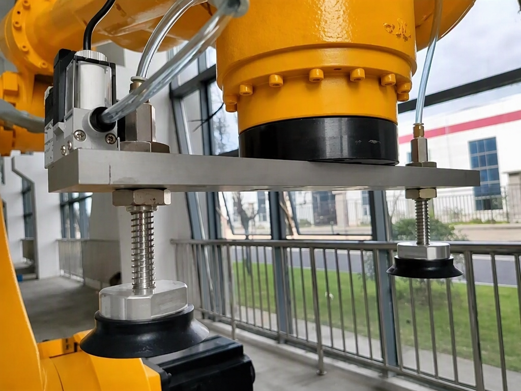
Vacuum grippers are widely used to lift steel sheets, glass, wood panels, cartons, and other workpieces. Yet the basic principleis often misunderstood: the vacuum inside a suction cup does not pull the workpiece upward. Instead, it lowers the pressureinside the cup, allowing the higher atmospheric pressure outside to press the cup against the workpiece.A vacuum cleaner works in much the same way. It does not literally “suck” dirt into the hose; atmospheric pressure pushes the dirt toward the lower-pressure region. This simple idea determines almost every important calculation in vacuum handling. In practice, engineers can control two main factors: the pressure difference and the effective contact area.
One Formula, Three Unit Systems
SMC presents the lifting-force calculation as:
W = P × S × 0.1 × 1/t
Here, W is the lifting force in newtons, P is the vacuum pressure in kilopascals, S is the suction-cup area in square centimetres,and t is the safety factor. SMC recommends a safety factor of at least 4 for horizontal lifting and at least 8 for vertical lifting.
A similar formula used in domestic technical materials is:
F = 0.1 × A × P
where A is the effective suction area in square centimetres and P is the vacuum pressure in kilopascals. For vertical lifting,friction must also be considered:
F = μ × 0.1 × A × P
The friction coefficient is critical when a workpiece is held vertically. Schmalz lists reference values of 0.2 to 0.3 for wet surfaces, 0.5 for wood, metal, glass, and stone, 0.6 for rough surfaces, and 0.1 to 0.3 for oily surfaces. Tameson gives similar guidance and also lists about 1.1 for sandpaper-like surfaces. These figures are only reference values. Real tests on the actual workpiece remain essential.
Weight Is Only the Starting Point
A workpiece’s mass is not the only load that a vacuum gripper must handle. Acceleration during lifting, stopping, or horizontal movement also increases the required holding force.
Schmalz expresses the theoretical holding-force requirement as:
FTH = m × (g + a) × S
where m is mass, g is gravitational acceleration, a is acceleration, and S is the safety factor. In one example, a 2.5-metre by 1.25-metre steel plate is lifted from a pallet with an acceleration of 5 metres per second squared. With a safety factor of 1.5, the required theoretical holding force is calculated as 1,363 newtons.The key rule is to calculate every relevant operating condition and use the most demanding one. On a high-speed production line, acceleration can become a large part of the total load. For a heavy, smooth workpiece, overlooking this factor can quickly
Why Safety Factors Come in Different Numbers
Vacuum-handling references often recommend different safety factors, but these values are not necessarily contradictory.They may apply to different calculation methods or loading conditions.When friction and acceleration are already included in the force calculation, a safety factor of at least 1.5 may be used for smooth, non-porous surfaces, while porous, rough, uneven, oily, or otherwise hazardous surfaces may require 2.0 or more.Other selection tables apply the factor directly to the lifting capacity. In that approach, typical recommendations are 4 to 6 times the load for horizontal handling, 8 to 10 times for vertical handling, 6 to 8 times for dynamic operation, and 10 times or more in high-risk environments.A further guideline accepts a 2:1 ratio for static holding, at least 4:1 when vertical lifting is combined with horizontal movement, and at least 8:1 when a suction cup is mounted horizontally while the workpiece is attached vertically.The important point is not to mix these approaches. A factor of 1.5 belongs to a calculation that already accounts for friction and acceleration; it should not be substituted blindly into a method designed around an 8-times direct capacity factor.
Post time: Oct-15-2026


