

Project Overview
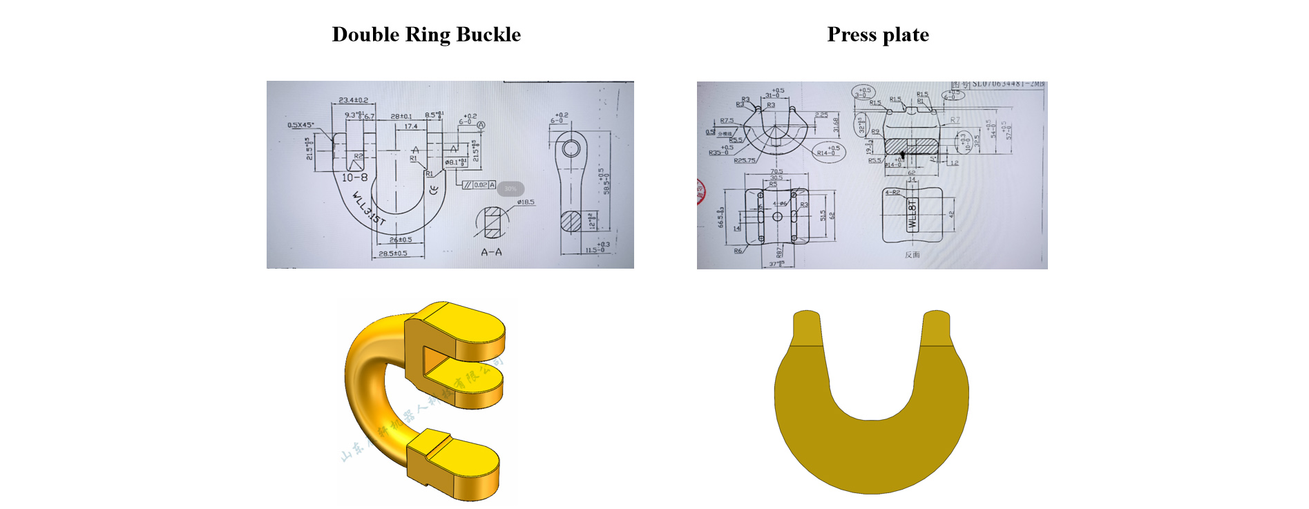
Workpiece Drawings: Subject to CAD drawings provided by Party A Technical requirements: Loading silo storage quantity ≥production capacity in one hour
|
Workpiece Type |
Specification |
Machining time |
Amount of storage/hour |
Number of wires |
Requirement |
|
SL-344 press plate |
1T/2T/3T |
15 |
240 |
1 |
Compatible |
|
5T/8T |
20 |
180 |
1 |
Compatible |
|
|
SL-74 Double Ring Buckle |
7/8-8 |
24 |
150 |
2 |
/ |
|
10-8 |
25 |
144 |
2 |
/ |
|
|
13-8 |
40 |
90 |
2 |
/ |
|
|
16-8 |
66 |
55 |
1 |
/ |
|
|
20-8 |
86 |
42 |
2 |
/ |
Workpiece drawing, 3D model
Scheme Layout
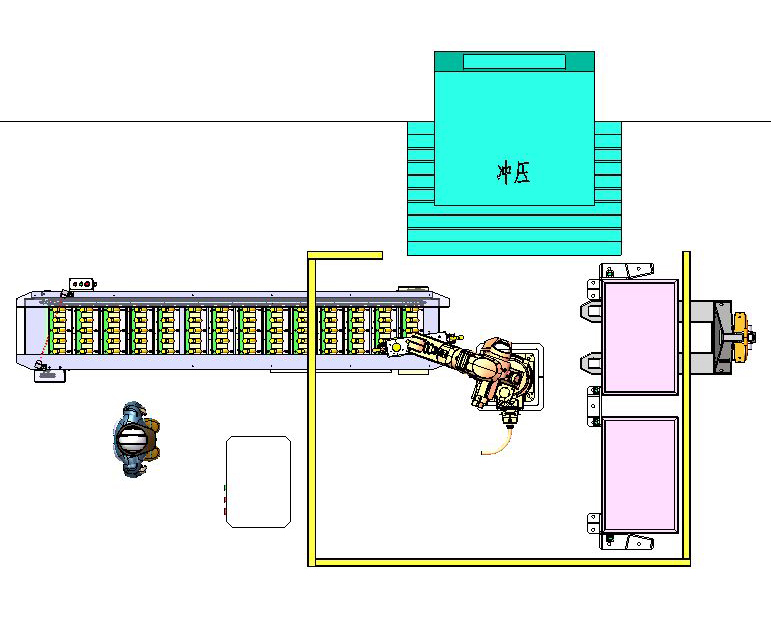
Description: The detailed dimension of land occupation shall be subject to the design.
Equipment List
Basket for temporary storage of partition plates
|
S/N |
Name |
Model No. |
Quantity. |
Remarks |
|
1 |
Robots |
XB25 |
1 |
Chenxuan (including the body, the control cabinet and demonstrator) |
|
2 |
Robot tong |
Customization |
1 |
Chenxuan |
|
3 |
Robot base |
Customization |
1 |
Chenxuan |
|
4 |
Electrical Control System |
Customization |
1 |
Chenxuan |
|
5 |
Loading conveyor |
Customization |
1 |
Chenxuan |
|
6 |
Safety fence |
Customization |
1 |
Chenxuan |
|
7 |
Material frame positioning detection device |
Customization |
2 |
Chenxuan |
|
8 |
Blanking frame |
/ |
2 |
Prepared by Party A |
Description: Table shows the configuration list of an individual workstation.
Technical description
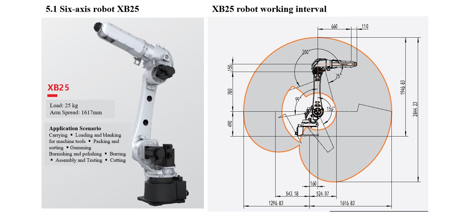
Six-axis robot XB25
Roboter XB25 als grundlegende parameter
|
Model No. |
Degree of Freedom |
Wrist Load |
Maximum working radius |
||||||||
|
XB25 |
6 |
25kg |
1617mm |
||||||||
|
Repeated positioning accuracy |
Body mass |
Protection grade |
Installation mode |
||||||||
|
± 0.05mm |
Approx. 252kg |
IP65(Wrist IP67) |
Ground, suspended |
||||||||
|
Integrated air source |
Integrated Signal Source |
Rated power of transformer |
Matched controller |
||||||||
|
2-φ8 air pipe (8 bar, solenoid valve for option) |
24-channel signal ( 30V, 0.5A ) |
9.5kVA |
XBC3E |
||||||||
|
Range of motion |
Maximum speed |
||||||||||
|
Shaft 1 |
Shaft 2 |
Shaft 3 |
Shaft 4 |
Shaft 5 |
Shaft 6 |
Shaft 1 |
Shaft 2 |
Shaft 3 |
Shaft 4 |
Shaft 5 |
Shaft 6 |
|
+180°/-180° |
+156°/-99° |
+75°/-200° |
+180°/-180° |
+135°/-135° |
+360°/-360° |
204°/S |
186°/S |
183°/S |
492°/S |
450°/S |
705°/S |
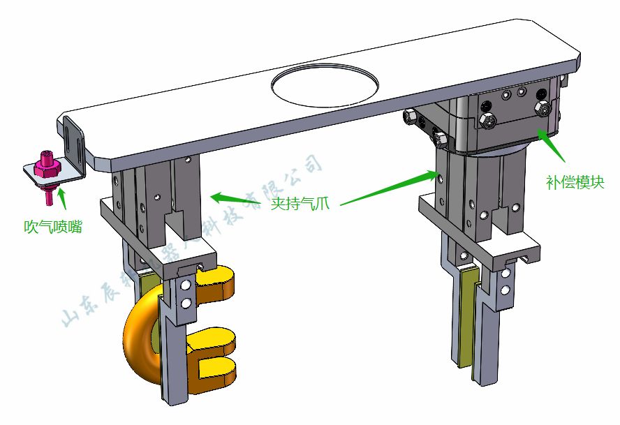
Robot tong
1. Double-station design, integrated loading and blanking, able to realize quick reloading operation;
2. Only applicable to clamp workpieces of specified specification, and the tong is only compatible with the clamping of similar workpieces within a certain range;
3. Power-off holding ensures that the product will not fall off in a short time, which is safe and reliable;
4. A group of high-speed pneumatic nozzles can meet the air blowing function in the machining center;
5. Polyurethane soft materials shall be used for clamping fingers to avoid pinching of workpiece;
6. The compensation module can automatically compensate workpiece positioning or the errors of the fixture and the variation of workpiece tolerance.
7. The diagram is for reference only, and the details shall be subject to the actual design.
| Technical Data* | |
| Order No. | XYR1063 |
| To connect flanges according to EN ISO 9409-1 | TK 63 |
| Recommended Load [kg]** | 7 |
| X/Y axis travel +/- (mm) | 3 |
| Center Retention Force (N] | 300 |
| Non-center Retention Force [N] | 100 |
| Maximum operating air pressure [bar] | 8 |
| Minimum operating temperature [°C] | 5 |
| Maximum operating temperature [°C] | +80 |
| Air volume consumed per cycle [cm3] | 6.5 |
| Moment of inertia [kg/cm2] | 38.8 |
| Weight [kg] | 2 |
| *All data is measured at 6 bar air pressure
**When assembled at the center |
Compensation module
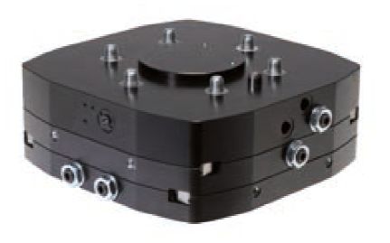
The compensation module can automatically compensate workpiece positioning or the errors of the fixture and the variation of workpiece tolerance.
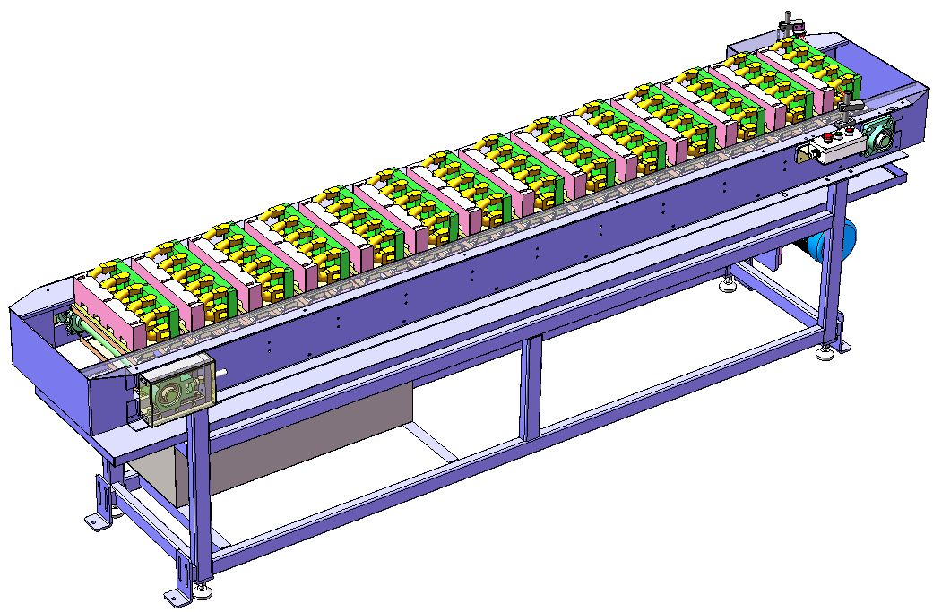
Loading and conveying line
1. Loading and conveying line adopts chain single-layer conveying structure, with large storage capacity, easy manual operation and high cost performance;
2. The designed quantity of products placed shall meet the production capacity of one hour. Under the condition of regular manual feeding in every 60 minutes, operation without shutdown can be realized;
3. The material tray is error-proofed, to assist manual convenient emptying, and silo tooling for workpieces of different specifications shall be adjusted manually;
4. Oil and water resistant, anti-friction and high-strength materials are selected for the feeding tray of the silo, and manual adjustment is required when producing different products;
5. The diagram is for reference only, and the details shall be subject to the actual design.
Electrical Control System
1. Including system control and signal communication between equipment, including sensors, cables, trunking, switches, etc.;
2. The automatic unit is designed with three-color alarm lamp. During normal operation, the three-color lamp displays green; and if the unit fails, the three-color lamp will display red alarm in time;
3. There are emergency stop buttons on the control cabinet and the demonstration box of the robot. In case of emergency, the emergency stop button can be pressed to realize the system emergency stop and send out alarm signal at the same time;
4. Through the demonstrator, we can compile many kinds of application programs, which can meet the requirements of product renewal and adding new products;
5. All emergency stop signals of the whole control system and the safety interlock signals between thef processing equipment and robots are connected to the safety system and the interlocked control is conducted through the control program;
6. The control system realizes the signal connection among the operating equipment such as robots, loading silos, tongs and machining machine tools;
7. Machine tool system needs to realize signal exchange with robot system.
Processing Machine Tool (provided by the user)
1. The machining machine tool shall be equipped with automatic chip removal mechanism (or to clean the iron chips manually and regularly) and automatic door opening and closing function (if there is machine door opening and closing operation);
2. During machine tool operation, iron chips are not allowed to wrap around workpieces, which may affect the clamping and placement of workpieces by robots;
3. Considering the possibility of chip wastes falling into the mould of the machine tool, Party B adds the air blowing function to the robot tongs.
4. Party A shall select appropriate tools or production technology to ensure reasonable tool life or changing tools by the tool changer inside the machine tool, so as to avoid affecting the quality of automation unit due to tool wear.
5. Signal communication between the machine tool and the robot shall be implemented by Party B, and Party A shall provide relevant signals of machine tool as required.
6. The robot conducts rough positioning when picking the parts, and the fixture of the machine tool realizes precise positioning according to the workpiece reference point.
Safety fence
1. Set the protective fence, the safety door, the safety lock and other devices, and carry out necessary interlocking protection.
2. The safety door shall be set at the proper position of the safety fence. All doors shall be equipped with safety switch and button, the reset button and the emergency stop button.
3. The safety door is interlocked with the system through safety lock (switch). When the safety door is opened abnormally, the system stops and gives an alarm.
4. Safety protection measures guarantee the safety of personnel and equipment through hardware and software.
5. The safety fence can be provided by Party A himself. It is recommended to weld with high-quality grid and paint with yellow warning stoving varnish on the surface.
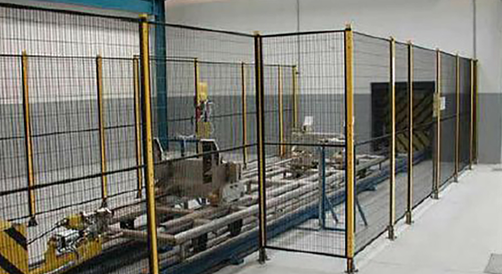
Safety fence
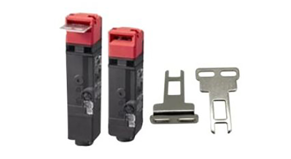
Safety lock
Safety fence Operating environment (provided by Party A)
| Power supply | Power supply: Three-phase four-wire AC380V±10%, voltage fluctuation range ±10%, frequency: 50HZ;The power supply of robot control cabinet shall be equipped with independent air switch; Robot control cabinet must be grounded with grounding resistance less than 10Ω; The effective distance between the power source and the robot electric control cabinet shall be within 5 meters. |
| Air source | The compressed air shall be filtered out of water, gas and impurities, and the output pressure after passing through FRL shall be 0.5~0.8Mpa; The effective distance between the air source and the robot body shall be within 5 meters. |
| Foundation | Treat with the conventional cement floor of Party A’s workshop, and the installation base of each equipment shall be fixed to the ground with expansion bolts; Strength of concrete: 210 kg/cm2;Thickness of concrete: More than 150 mm; Foundation unevenness: Less than ±3mm. |
| Environmental Conditions | Ambient temperature: 0~45 ℃;Relative humidity: 20%~75%RH (no condensation is allowed); Vibration acceleration: Less than 0.5G. |
| Miscellaneous | Avoid flammable and corrosive gases and fluids, and do not splash oil, water, dust, etc.; Do not approach the source of electrical noise. |


